
SDR Transmitter Modulation Monitor
This project is a handy little Transmitter Modulation Monitor: A self-contained device, which displays the frequency characteristics of our transmitted signal. It is an important piece of test equipment for any transmitting station as it ensures that the transmitter is set up and used correctly. It provides a "reverse waterfall" display showing the signal power, in shades from blue to yellow, with the signal frequency across the screen and the time history shown from bottom to top. The patterns move up the screen for 20 seconds, with the most recent information shown at the bottom. This device is a spin-off from our SDR receiver project. See the GippsTech 2018 Build your own SDR Presentation for details. It costs around AU$150 and is fascinating and educational to watch.

Components of the Modulation Monitor:
- Micro USB 5V power Supply
- RTL-SDR Dongle
- USB Extension Cable
- Raspberry Pi 3 computer
- Micro SDHC Card
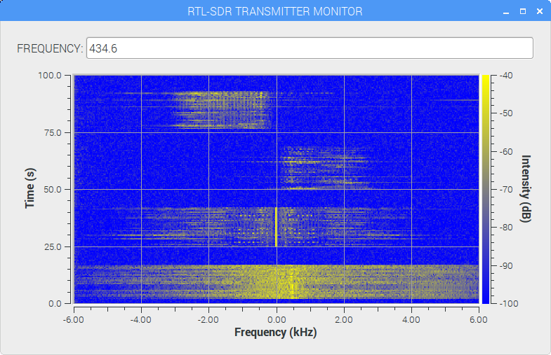
Transmitter Modulation Monitor display:
- Upper Sideband (USB)
- Lower Sideband (LSB)
- Amplitude Modulation (AM)
- Frequency Modulation (FM)
Note: The LSB and USB signals show some "splatter" outside their nominal 3kHz bandwidth and also into their opposite sidebands. It is about 30dB down, but it should be better than that, indicating some overmodulation. It is possible that the students were speaking too close to the microphone. The AM signal has about an 8kHz bandwidth and the FM signal has about a 12kHz bandwidth. They seem OK.

This is the GNU Radio flowgraph for the Transmitter Modulation Monitor receiver