
SARCTRAC Mk4
Satellite Antenna Rotator Controller and TRACker
This page is currently under construction
Introduction
For several years we were content to set up our portable SARCTRAC system whenever we wanted to work satellites. However, for a permanent installation, we needed a heavy-duty rotator which could handle a couple of cross polarised Yagi antennas.
SARCTRAC Mk4 is our heavy-duty, integrated, satellite tracking system. This is a DIY project only. It will not be available as a kit or a fully-assembled product. The software will not be available. We publish the details here for those who wish to copy our design or seek inspiration for their own designs.
 SARCTRAC Mk4 CAD Model
See it in a 3D Viewer (85MB!) Controls: Double-Click to centre. Left-Click to rotate. Wheel to zoom.
SARCTRAC Mk4 was designed entirely in FreeCAD and developed entirely on our dining room table! The software was written in C++ using the Arduino IDE for the ESP8266. We cut and machined all the Aluminium stock ourselves in the garage, using nothing but a cut-off saw and a drill press, although, we had some help from John at Lightning Laser Cutting to cut the six panels for the cover.
The general arrangement and the names of the main components are shown in the following diagram.
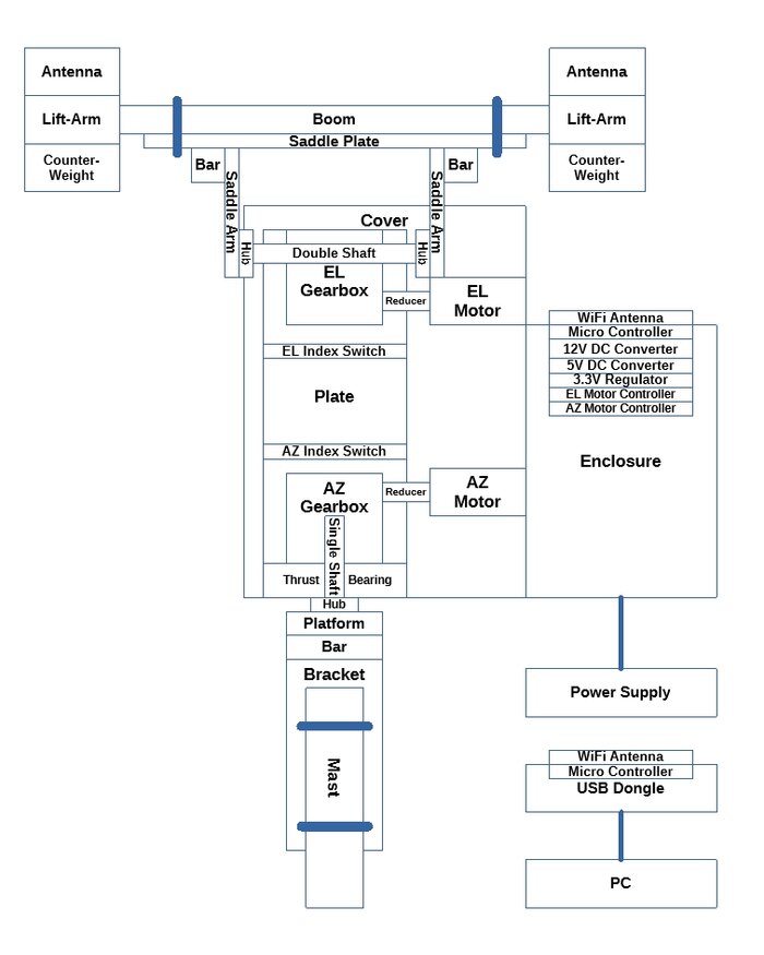
Component General Arrangement and Nomenclature

FreeCAD Development

Software Development
SARCTRAC Mk4 Video
Components
The key elements would be a through-shaft gearbox for the elevation boom, some powerful motors and electrical motor drivers. After some searching, we couldn't believe that almost everything we needed was available online at stepperonline for very reasonable prices. The items arrived beautifully packed in less than a week.
These right-angle worm gearboxes are amazing. They are used for both the azimuth and elevation shafts. They have a single 11mm keyed input and a double 14mm keyed output. They have a flange to directly fit a NEMA 23 stepper motor on the input. We chose the 50:1 gear ratio. They have a max torque of 1.7 kg.m and a max radial load of 128 kg. A 11mm to 8mm reducer is required to fit the common size of NEMA 23 stepper motor. They can take either a single or double output shaft.
Now this is probably an overkill, but we know that despite our best efforts water will eventually get in. The input and output hollow shafts of this gearbox do not look like stainless steel to us. They could be mild steel. So, just a precaution, we coated them - and just about everything else in this project - with Tef-Gel. We love it because, unlike grease, it keeps everything from corrosion.

NMRV30-G50-D11 50:1 Thru-Shaft Worm Gearbox
This is the double output shaft for the elevation gearbox. To be able to fit the shaft through the gearbox, it comes without the key blocks or circlips installed. Care should be taken to fit the key blocks in a parallel fashion, using a vice or press, as once they are in - they are in. It is unlikely that there will be much axial force on this shaft as it is horizontal. The ends of the shaft are drilled and tapped, which provides an additional way to keep the hubs, with their small set-screws, from falling off.
Next is the single output shaft for the azimuth gearbox. It comes with all the key blocks installed. This shaft is mounted vertically and would normally take the full weight of the rotator and antenna assembly. Care must be taken to ensure that axial forces on this shaft are not transferred to the gearbox bearings. Instead, careful fitment of a thrust bearing and packing washers around this shaft ensures that any axial force is transferred to the gearbox housing. More on this later.

RV30-AB Keyed Double Output Shaft for the Elevation Gearbox

RV30-AS Keyed, Single Output Shaft for the Azimuth Gearbox
This is a unique item which fits the 14mm keyed shafts. It is a stainless steel hub. It provides a flange with six M5 tapped holes to attach the rotator saddle assembly and to attach the rotator itself to the mast bracket. There is also a tapped set-screw hole to secure the shaft. Surprisingly it is not available from stepperonline as it fits all their gearbox shafts. A total of three are required.

18104 Keyed 14mm S/S Shaft Hub
This is the thrust bearing to take the vertical load of the rotator and antenna assemblies. It comes in three parts: Two ball-race rings with different inner-diameters and a ball-bearing assembly. The smaller inner-diameter ball-race ring is mounted on the top in this application. The ball-bearing assembly is packed with grease prior to assembly.
To make the thrust bearing to take all the vertical load it must be stacked with four large flat washers to be the same length as the vertical shaft. The shaft itself is free to move up and down inside the key way. The circlip on the shaft must also be free so as not to take any load. These M30 stainless steel washers have the same outside diameter as the thrust bearing and have a large-enough inner diameter to take the shaft.
The thrust bearing itself was housed in short piece of PVC pipe, secured to the azimuth gearbox housing with silicone sealant. A small gap at the bottom is required to permit rotation of the rotator assembly. While it is not perfectly sealed, it should prevent ingress of some rain and dust. It will need to be inspected every few years or so.

51206 Thrust Bearing

M30 x 56mm x 3mm Flat S/S Washer
These are NEMA 23, 2-phase stepper motors have a holding torque of 2.4 N.m, a rated current of 4.0 A and a step angle of 1.8 degrees. That is 200 steps per revolution. The output shaft is 8 mm diameter with a flat key. We designed for a maximum rotator speed of 2.0 RPM so, with a 50:1 gearbox, the maximum motor speed will be 100 RPM, running at 333 steps per second.
The gearbox has an 11mm diameter input, so an 11mm to 8mm adaptor is required to fit the motor. These adaptors are manufactured using Electrical Discharge Machining (EDM). Unfortunately they have a very rough finish and we found them impossible to assemble onto the motor shafts. We discovered, online, that others have had exactly the same problem. There was nothing else for it other than to attack the surfaces with a small rotary grinding stone attached to a Dremel tool. It took us quite a while, but it worked out all right in the end. Again, we protected all these surfaces with Tef-Gel. We also made two motor gaskets out of neoprene.

23HS32-4004S NEMA 23 Stepper Motor

RV30-K11-D8 Shaft Sleeve Adaptor 11mm to 8mm
These stepper motor drivers are great. They handle up to 4.5 A from 18-50 V. Which is good, because we decided to run the stepper motors off 48 V DC to keep the current down and the performance up. They have opto-isolated step and direction control inputs, which work down to 3.3 V suitable for the ESP8266 microcontroller. The main reason for using these devices is the intelligent idle current reduction, which keeps the motors cooler.

DM542T Stepper Motor Driver
Of course we needed a 48 V power supply, which was also available at stepperonline. This power supply will be located inside the house, providing safe, low voltage to the rotator outside. It will be housed in a suitable enclosure.

S-400-48 48V DC Power Supply
The controller electronics were mounted in a diecast aluminium enclosure. The enclosure houses:
- Two stepper motor controllers
- A Veroboard electronics assembly comprising:
- An ESP8266 Wemos D1 Mini Pro microcontroller
- A 80 V to 12 V DC/DC converter
- A 80 V to 5 V DC/DC converter
- A 5 V to 3.3 V linear regulator (Since the ESP8266 onboard unit does not provide sufficient current)
- A 48V opto-isolated, power supply detect circuit (which is used to to save the rotator position prior to power-down)
- A 2.4GHz external WiFi antenna
In addition there is also a ESP8266 Wemos D1 Mini providing a USB WiFi dongle for the PC to communicate with the controller.
Note: We do not provide any details of the electronics or software for the controller or the USB WiFi Dongle.

Deltron 483-0100 Diecast Enclosure with Flange
The ESP8266 Wemos D1 Mini Pro (clone) was selected as it has an external 2.4 GHz antenna connection. Note: A zero ohm SMT resistor has to be relocated to enable this feature. There are just sufficient digital I/O pins on this device to run the stepper motors with inputs from the Az and El index switches and the power-down detector. Even so, some external pull-up resistors and diodes are required to isolate some pins from the external devices at power up.
The WiFi antenna is conveniently provided with an SMA connector for mounting the antenna on the enclosure and a short cable.

Wemos D1 Mini/Mini Pro 16MB ESP8266/ESP12 WiFi NodeMCU

2.4GHz WiFi Cable and Antenna
The main feature of these XL7015 adjustable DC/DC converters is that they can handle an input voltage of up to 80 V (Do not use LM2596 DC/DC converters as they can only handle 45 V). There are two. The one set to 12 V provides power to the hall-effect switches. The one set to 5 V provides power to the ESP8266.
Note: An additional 3.3 V linear regulator also provides power to the ESP8266. While the ESP8266 has an on-board 3.3 V regulator, it does not provide sufficient current to run the WiFi. Extensive testing showed that both 5 V and 3.3 V external supplies were required to reliably boot up the WiFi. Perhaps it was because these boards were clones. Who knows?

XL7015 DC-DC Converter Step-Down Module 5V-80V Wide Voltage Input
Stepper motors, of course, can only provide relative positioning from a known starting point. These Hall-Effect magnetic switches provide an indexing signal when the rotator is in the North/Horizontal position. There are neodymium magnets embedded into the rotator saddle assembly and the mast bracket, which align with these switches in this position. The software in the rotator has to use these switches to establish this starting point. However, there are some issues: The index signal output from these devices is about 20 degrees wide with a few degrees of hysteresis. A calibration function would run the rotator either side of the signal to determine the central position within less than a degree accuracy. This process worked out very well and was quite repeatable. To avoid having to run this calibration cycle every time the rotator was started, it was decided to record it's last known position every time the 48 V power was removed.

NJK-5002C Hall Effect Switch NPN Output 6V-36V
The chosen stepper motors and gearboxes produce so much torque that they could easily destroy the antenna system if they were permitted to drive the rotator out of bounds. Despite all the precautions taken in software to avert such a catastrophe, an independent fail-safe mechanism is required. A simple solution is to attach end-stops to the saddle assembly. These stop the rotator moving when they contact the sides of the cover.
End-Stops
We decided to provide a cover for the gearboxes and motors to keep them out of the weather. The cover is made of 2mm aluminium plate. It was professionally laser-cut from a 2D DXF file exported directly from freeCAD. We were absolutely delighted with the results, which we could have never achieved ourselves. The panels are fitted together using corner blocks cut from the same 16 mm aluminium bar used on the rotator assembly. Eight blocks were cut 14 mm long with a cut-off saw. They were then drilled, three ways, on our drill press. Afterwards, they were tapped with a battery-electric hand-drill, back and forth many times, on the lowest available torque setting. And we only broke one 3mm tap!
The down-side of adding this cover was that the it interfered with the downward swing in the elevation calibration cycle. So we had to modify the saddle plate and its assembly by mounting the corner blocks on the outside of the saddle arms. It worked out well, however, the original version still appears in some of the earlier photos.

Cover Panels - Laser Cut
These dual-band, directional, Yagi antennas have 4 elements on the 2 metre band and seven elements on the 70 centimetre band. They are mounted on lift-arms made from 25mm aluminium square hollow section, each with a counterweight. The antenna assemblies are mounted to the horizontal rotator boom. The mounting point is slightly behind the balance point, providing an initial downward force to reduce backlash.

Dual Band Yagi Antenna 2m/70cm
These 1kg cast-iron weights are made for exercise weight belts. They are perfect for use as a counterweight. They are drilled and fitted to the rear of the antenna lift-arms.

1kg Counterweight
Downloads
SARCTRAC Mk 4 FreeCAD files can be downloaded from here (51MB. Includes 23 Drawings. Last updated 28 May 2024).
SARCTRAC Mk 4 Parts List file can be downloaded from here (15kB Excel format. Last updated 17 May 2024).
Please note: The software for this project is not available.
These files are provided as-is, without any warranty and may not be fit for any purpose whatsoever. They may be change at any time without notice. No support is provided. No responsibility is accepted. Prices shown are indicative only. No suppliers are endorsed. The main project file is Rotator.FCStd.
Assembly
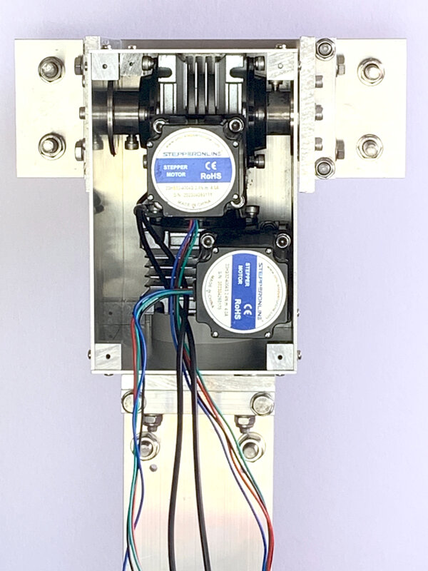
Pictures of the assembly:
- The rotator with the rear cover removed showing the assembly of the laser-cut cover plates using drilled and tapped corner blocks.
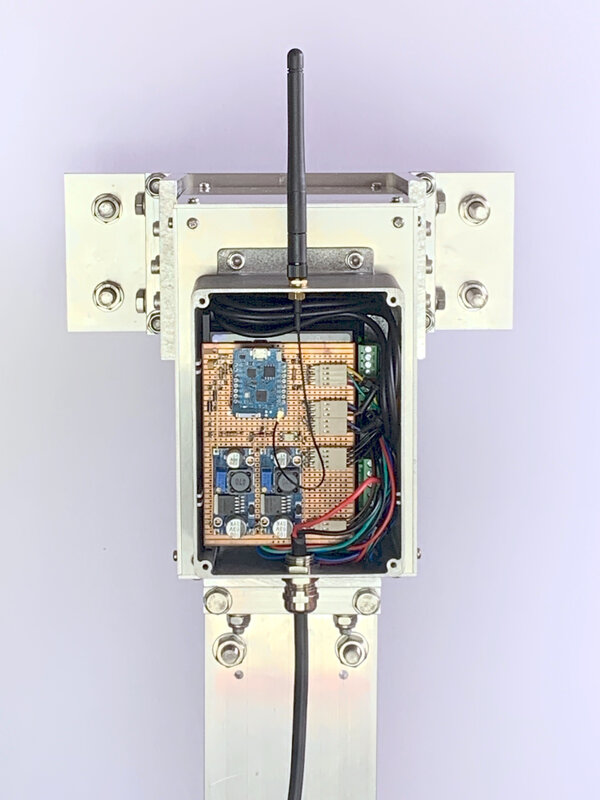
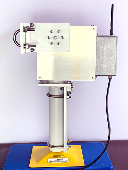
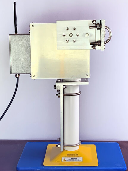
- The rotator controller with the rear cover removed showing the motor drivers and Arduino controller inside and the WiFi antenna and power cable gland on the outside.
- Note the saddle blocks are now mounted on the outside of the saddle arms to avert contacting the cover during the calibration cycle.
Pictures of the assembly:
- Left Side
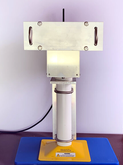
- Front showing the saddle plate
- Right Side
- Note that a sturdy desk stand was required for testing. It was made out of a yellow automotive axle stand and some 60mm OD PVC DWV pipe.
Video of the automatic sensor calibration process: Initiated by sending the C command from a PuTTY serial terminal. The rotator first moves right and left, then moves up and down, accurately finding the centre point of the hall-effect sensors. The results are stored in Flash memory on the ESP8266.
Software
The rotator control and communications functions are provided by two ESP8266 microcontrollers, using software written in C++ on the Arduino IDE. The system comprises a SARCTRAC Server, running inside the control unit of the rotator, and a SARCTRAC USB WiFi Dongle connected to a PC. These processors provide a dedicated WiFi link for communications between the PC and Rotator. The SARCTRAC Server has a WiFi Access Point and Telnet Server, a command interpreter and a stepper motor position and speed controller. The SARCTRAC USB WiFi Dongle has a WiFi Client and Telnet Client. The rotator can be controlled via a simple user interface using a serial terminal, such as PuTTY running on the PC. However, the controller also transparently accepts AMSAT EasyCommII protocol commands from a tracker program, also running on the PC.
Note: We do not provide any details of the electronics or software for the controller or the USB WiFi Dongle.
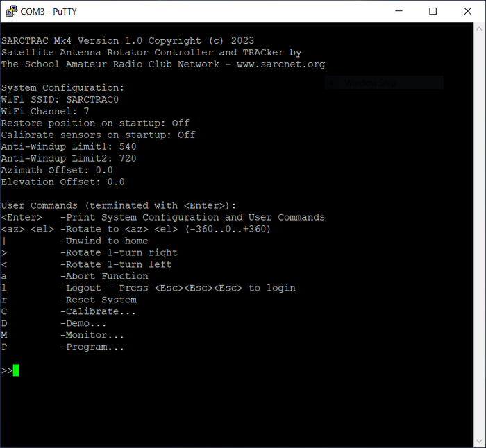
SARCTRAC Access via a serial terminal program
Tracker
SARCTRAC Mk1 and Mk2 used to have their own integrated web servers and tracker applications. By popular demand, SARCTRAC Mk3 was able to use any third-party, external tracker. However, for SARCTRAC Mk4, we decided to build a completely new tracker, from scratch (with some help), in Python. We didn't need all those fancy maps and footprint displays, just 6-hour satellite prediction, pass selection, rotator control, rig frequency and mode control. Of great importance to us was to be able to quickly find and select the active frequencies and modes needed for a selected satellite. Previously this involved a lot of Internet searching. SARCTRAC now makes the whole operation very easy!
Operation
- Enter the name of your location and its latitude, longitude and altitude.
- Press Add. This location will be saved for future selection.
- Select the category of satellites of interest. The current categories are: "100 (or so) Brightest, ARGOS Data Collection System, Active Geosynchronous, Active Satellites, Amateur Radio, Analyst Satellites, Beidou, COSMOS 2251 Debris, Chinese ASAT Test Debris (FENGYUN 1C), CubeSats, Disaster Monitoring, Earth Resources, Education, Engineering, Experimental Comm, GLONASS Operational, GNSS, GOES, GPS Operational, Galileo, Geodetic, Globalstar, Gorizont, IRIDIUM 33 Debris, Intelsat, Iridium, Iridium NEXT, Last 30 Days' Launches, Miscellaneous Military, Molniya, NOAA, Navy Navigation Satellite System (NNSS), OneWeb, Orbcomm, Other Comm, Other Satellites, Planet, Radar Calibration, Raduga, Russian ASAT Test Debris (COSMOS 1408), Russian LEO Navigation, SES, SatNOGS, Satellite-Based Augmentation System (WAAS/EGNOS/MSAS), Search & Rescue (SARSAT), Space & Earth Science, Space Stations, Spire, Starlink, Swarm, Tracking and Data Relay Satellite System (TDRSS)". These categories are provided by Celestrak and may change from time to time!
- Active satellite pass predictions are shown for the selected category. Note: Active satellites are satellites (more than 250 of them) for which active frequency data is available. These satellites are only found in the categories shown in bold above.
- All active satellite passes, within the next 6 hours, will be displayed including:
- AOS - The Acquisition Of Signal time displayed as Hours:Minutes:Seconds in local time format.
- LOS - The Loss Of Signal time displayed as Hours:Minutes:Seconds in local time format.
- The satellite name.
- The pass duration displayed as Minutes:Seconds.
- the Maximum elevation of the pass in degrees.
- The row will be displayed in bold if the satellite is currently above the local horizon.
- The row will be removed when the satellite sets below the local horizon.
- The 6-hour prediction list will be updated every 10 minutes.
- Scroll the display with the mouse wheel.
- Select a satellite by name from the list. Note: The first satellite in the category is selected by default. Some satellites have alternative names, as shown in brackets. The selected satellite is added to the active satellite pass predictions even if it is inactive or has no frequency data.
- Alternatively, select a satellite by clicking on a satellite pass.
- The selected satellite information will be displayed, if it is available from JE9PEL.
- Click on a single frequency to select it.
- Click on a frequency range to select the mid point. e.g. 435.3065-435.3235 will select 435.315.
- Click on a frequency list again to select the next item. e.g. 144.390/437.225* will select the next item.
- An asterisk (*) indicates the preferred frequency or mode.
- Selected frequencies will be automatically inserted into the appropriate TX Freq and RX Freq below.
- Scroll the display with the mouse wheel.
- Edit the TX Freq and RX Freq if required.
- Select the TX Mode and RX Mode, manually, from 'USB', 'LSB', 'CW', 'FM' or, 'WFM'
- Select the rotator type, mode (-180..180 or 0..360), port and baudrate. See below for supported rig types.
- Select the rig type, mode (Main/Sub or Split), port and baudrate. See below for supported rig types.
- Press the Start/Stop button to toggle automatic tracking control.
- The selected satellite azimuth and elevation are displayed in decimal degrees. These are used for rotator control.
- The TX and RX frequencies, corrected for the Doppler effect, are displayed in MHz. These are used for rig control.
- With automatic tracking stopped, the azimuth and elevation can be entered or selected manually: Useful for pointing at geostationary satellites or for parking the antenna.
- The rotator and rig control is enabled by separate buttons. Green indicates the control is enabled. Red indicates the control is disabled.
- Press the Rotator and Rig buttons to toggle the control function.

SARCTRAC Tracker App
Supported Rotator Types
The following rotator types are supported (however not all rotators are suitable for satellite communications):
AMSAT IF-100, AMSAT LVB, BG5DIW GRBLTRK, CNCTRK CNCTRK, Celestron NexStar, DF9GR ERC, DG9OAA Ether6, EA4TX ARS, F1TE GS232/F1TE, FoxDelta GS232/ST2, Green Heron, Hamlib Dummy, Hamlib EasycommI, Hamlib EasycommII, Hamlib EasycommIII, Hamlib NET, Heathkit HD, Hy-Gain DCU-1/DCU-1X, Hy-Gain DCU2/DCU3/YRC-1, Idiom Press, LA7LKA ts7400, M2 RC2800, M2 RC2800_EARLY_AZ, M2 RC2800_EARLY_AZEL, Meade LX200/Autostar, Prosistel Combi-Track, Prosistel D, Radant AZ-1/AZV-1, SARtek SARtek-1, SPID MD-01/02, SPID Rot1Prog, SPID Rot2Prog, SatEL SatEL, Various GS-232, WA6UFQ PcRotor, XQ2FOD Fodtrack, Yaesu GS-232A, Yaesu GS-232B, Yaesu/Kenpro GS-23, Yaesu/Kenpro GS-232, iOptron iOptron
Supported Rig Types
The following rig types are supported (however not all rigs are suitable for satellite communications):
ADAT www.adat.ch, AE9RB Si570, AMSAT-UK FUNcube, AOR AR2700, AOR AR3000A, AOR AR3030, AOR AR5000, AOR AR5000A, AOR AR7030, AOR AR8000, AOR AR8200, AOR AR8600, AOR SR2200, Alinco DX-77, Alinco DX-SR8, AmQRP DDS-60, Barrett 2050, Barrett 4050, Barrett 950, CODAN Envoy, CODAN NGT, Coding Technologies, DTTS Microwave, Dorji DRA818U, Dorji DRA818V, Drake R-8A, Drake R-8B, ELAD FDM-DUO, Elecraft K2, Elecraft K3, Elecraft K3S, Elecraft K4, Elecraft KX2, Elecraft KX3, Elecraft XG3, Elektor Elektor, FLRig FLRig, FiFi FiFi-SDR, Flex-radio SDR-1000, FlexRadio 6xxx, FlexRadio/ANAN PowerSDR/Thetis, Funkamateur FA-SDR, GOMSPACE GS100, Hamlib Dummy, Hamlib NET, Hilberling PT-8000A, HobbyPCB RS-HFIQ, Icom IC, Icom IC-1275, Icom IC-271, Icom IC-2730, Icom IC-275, Icom IC-375, Icom IC-471, Icom IC-475, Icom IC-575, Icom IC-7000, Icom IC-703, Icom IC-705, Icom IC-706, Icom IC-706MkII, Icom IC-706MkIIG, Icom IC-707, Icom IC-7100, Icom IC-718, Icom IC-7200, Icom IC-725, Icom IC-726, Icom IC-728, Icom IC-729, Icom IC-7300, Icom IC-735, Icom IC-736, Icom IC-737, Icom IC-738, Icom IC-7410, Icom IC-746, Icom IC-746PRO, Icom IC-751, Icom IC-756, Icom IC-756PRO, Icom IC-756PROII, Icom IC-756PROIII, Icom IC-7600, Icom IC-761, Icom IC-7610, Icom IC-765, Icom IC-7700, Icom IC-775, Icom IC-78, Icom IC-7800, Icom IC-781, Icom IC-7850/7851, Icom IC-820H, Icom IC-821H, Icom IC-910, Icom IC-9100, Icom IC-92D, Icom IC-970, Icom IC-9700, Icom IC-F8101, Icom IC-M700PRO, Icom IC-M710, Icom IC-M802, Icom IC-M803, Icom IC-PCR100, Icom IC-PCR1000, Icom IC-PCR1500, Icom IC-PCR2500, Icom IC-R10, Icom IC-R20, Icom IC-R30, Icom IC-R6, Icom IC-R7000, Icom IC-R71, Icom IC-R7100, Icom IC-R72, Icom IC-R75, Icom IC-R8600, Icom IC-R9000, Icom IC-R9500, Icom IC-RX7, Icom ICR-8500, Icom ID-31, Icom ID-4100, Icom ID-51, Icom ID-5100, JRC JST-145, JRC JST-245, JRC NRD-525, JRC NRD-535D, JRC NRD-545, KTH-SDR kit, Kachina 505DSP, Kenwood R-5000, Kenwood TH-D72A, Kenwood TH-D74, Kenwood TH-D7A, Kenwood TH-F6A, Kenwood TH-F7E, Kenwood TH-G71, Kenwood TM-D700, Kenwood TM-D710(G), Kenwood TM-V7, Kenwood TM-V71(A), Kenwood TRC-80, Kenwood TS-140S, Kenwood TS-2000, Kenwood TS-440S, Kenwood TS-450S, Kenwood TS-480, Kenwood TS-50S, Kenwood TS-570D, Kenwood TS-570S, Kenwood TS-590S, Kenwood TS-590SG, Kenwood TS-680S, Kenwood TS-690S, Kenwood TS-711, Kenwood TS-790, Kenwood TS-811, Kenwood TS-850, Kenwood TS-870S, Kenwood TS-890S, Kenwood TS-930, Kenwood TS-940S, Kenwood TS-950S, Kenwood TS-950SDX, Kenwood TS-990S, Lab599 TX-500, Lowe HF-235, M0NKA mcHF, Malachite DSP, Microtelecom Perseus, N2ADR HiQSDR, OpenHPSDR PiHPSDR, Optoelectronics OptoScan456, Optoelectronics OptoScan535, Philips/Simoco PRM8060, QRPLabs QCX/QDX, RFT EKD-500, Racal RA3702, Racal RA6790/GM, Radio Shack, Rohde&Schwarz EB200, Rohde&Schwarz EK895/6, Rohde&Schwarz ESMC, Rohde&Schwarz XK2100, SAT-Schneider DRT1, SDRPlay SDRUno, SigFox Transfox, Skanti TRP, Skanti TRP8000, SoftRock Si570, TAPR DSP-10, TRXManager TRXManager, Ten-Tec Delta, Ten-Tec Omni, Ten-Tec RX-320, Ten-Tec RX-331, Ten-Tec RX-340, Ten-Tec RX-350, Ten-Tec TT-516, Ten-Tec TT-538, Ten-Tec TT-550, Ten-Tec TT-565, Ten-Tec TT-585, Ten-Tec TT-588, Ten-Tec TT-599, Uniden BC245xlt, Uniden BC250D, Uniden BC780xlt, Uniden BC895xlt, Uniden BC898T, Uniden BCD-396T, Uniden BCD-996T, Vertex Standard, Watkins-Johnson WJ-8888, Winradio WR-G313, Xiegu G90, Xiegu X108G, Xiegu X5105, Xiegu X6100, Yaesu FRG-100, Yaesu FRG-8800, Yaesu FRG-9600, Yaesu FT-100, Yaesu FT-1000D, Yaesu FT-1000MP, Yaesu FT-2000, Yaesu FT-450, Yaesu FT-450D, Yaesu FT-600, Yaesu FT-650, Yaesu FT-710, Yaesu FT-736R, Yaesu FT-747GX, Yaesu FT-757GX, Yaesu FT-757GXII, Yaesu FT-767GX, Yaesu FT-817, Yaesu FT-818, Yaesu FT-840, Yaesu FT-847, Yaesu FT-847UNI, Yaesu FT-857, Yaesu FT-890, Yaesu FT-891, Yaesu FT-897, Yaesu FT-897D, Yaesu FT-900, Yaesu FT-920, Yaesu FT-950, Yaesu FT-980, Yaesu FT-990, Yaesu FT-991, Yaesu FTDX-10, Yaesu FTDX-101D, Yaesu FTDX-101MP, Yaesu FTDX-1200, Yaesu FTDX-3000, Yaesu FTDX-5000, Yaesu FTDX-9000, Yaesu MARK-V, Yaesu VR-5000, mRS miniVNA
Acknowledgements
Presented by: The School Amateur Radio Club Network:
We have actually been building our own satellite trackers, originally from first principles, since 1983. In 1988 we converted the SGP4 propagation model, by Dr. T.S. Kelso et al, from Fortran IV to Turbo Pascal 3, running it on a home-built, Z-80, CP/M computer into a couple of TV antenna rotators. We used to download the NORAD, two line orbital element sets with a 300 baud modem connected via the phone lines to the the Celestial BBS. Working with satellites is fun and you can learn a lot. We would like to thank all those who have helped us along the way.
Celestrak - By Dr. T.S. Kelso. Satellite orbital elements since 1985TKinter - By John Ousterhout. The standard Python interface
Skyfield - By Brandon Rhodes - Elegant Astronomy for Python
HAMLIB - Ham radio control libraryJE9PEL - Satellite frequency list
History
We first introduced our free, Arduino-based, "Mini Satellite-Antenna Rotator" in 2015. It was a great success, with over 1000 radio enthusiasts from around the world building one. Unfortunately, sourcing the correct components, compiling and uploading the software and calibrating the sensor was too much for many who attempted building it. Let alone the pitfalls of setting up and using third-party, satellite-tracking software. And, as much as we love helping our readers out, we realised that we were spending more time supporting them than developing new projects for the kids.
We partly solved that problem by designing an integrated satellite tracking system that just works: SARCTRAC Mk1 took us over 15 months to develop and was the second generation of our 3D-sensor based antenna rotator. It was half the size of the original unit with many new features. SARCTRAC Mk1 was offered as a DIY kit with all the parts and software required. Unfortunately, it only supported one type of radio: The Yaesu FT-817 and was only suitable for the experienced builder. So, we were still confronted with a large support effort.
In 2021, we produced SARCTRAC Mk3a. We totally revised the project addressing many user, hardware, software, integration, production and support issues: Most readers just wanted the cheapest-possible, AZ-EL rotator to steer their hand-held satellite antennas and to use it with their own PC-based, satellite tracking and radio control applications. Quite a few had problems configuring SARCTRAC Mk2 to connect to their home WiFi network. They wanted a dedicated, wireless solution that did not require the use of a WiFi router. Some had problems when the cables got wound up. They needed a fool-proof safety cut-off device. SARCTRAC Mk2, with a built-in Raspberry Pi 3B+ tracker and web-server, required a lot of power, a large heatsink and was noisy on the VHF/UHF satellite bands. So, we went back to basics and designed a cheap, low-power, low-noise, rotator, with a dedicated wireless link, that would work with popular, many free, PC-based, satellite-tracking applications.
In 2023, we abandoned production of SARCTRAC due to on-going supply and support problems. We realised that our mission was actually getting kids into radio and electronics and not selling rotators. However, we continued development of SARCTRAC for our own use, specifically a heady-duty model we called SARCTRAC Mk4. We designed it entirely in FreeCAD and built our first prototype in January 2024.
Setup
Features
- Automatically rotates a satellite antenna under the control of a PC-based, satellite tracking application.
- Can be remotely controlled by popular, (mostly) free, Satellite Tracking applications on a Windows or Linux PC, Laptop, Raspberry Pi etc.
- Includes a dedicated WiFi USB dongle - Wireless remote control up to 30m/100ft away.
- Built in WiFi Access Point - No WiFi router or hotspot required.
- Emulates AMSAT EasyCommII rotator protocol – Steers antenna and provides antenna position feedback
- Tested with PstRotator™, Gpredict™, SatPC32™ and Orbitron™. Others TBA.
- Built-in serial terminal utility for manual user control, debug, monitoring, calibration, configuration and simulation.
- Built in microcontroller - Low noise, fast start up and no shutdown procedure required.
- Provides an intelligent anti-windup algorithm - Automatically unwinds the cables between passes.
Links
Specifications
- WiFi mode: 802.11b/g/n. WiFi band: ISM2.4GHz. WiFi range: 30 m (100 ft) typical.
- Rotation range: Azimuth +/-360 degrees. Elevation -30 to 150 degrees.
- Rotation speed: 2 RPM (12 degrees per second) azimuth and elevation.
- Rotation torque: 1.7 kg.m
- Rotation load: 130 kg.m
- Rotation accuracy: < +/- 0.1 Degrees
- Rotation mode: Shortest-path with configurable anti-windup algorithm.
- Start-up time: 10 seconds. No shutdown time required.
- Rotator emulation - Serial protocol: AMSAT EasyCommII with position feedback - 9600/N/8/1.