
Introduction
A natural spin-off from all of our Raspberry Pi, Arduino and ESP8266 projects was the idea of building our own Home Automation System. We wanted to learn to use the best techniques to intelligently control and automate existing household appliances such as:
- Solar inverters;
- Smart meters;
- Smart plugs;
- Air conditioners;
- Smoke detectors;
- Garage door opener;
- Video surveillance and
- Security systems.
Requirements
- We need to monitor and control the appliances in our home.
- We need a graphical user interface to access these appliances from our smart phones when we are at home or away from home.
- We need real-time alerting of any potential security issues.
- We need local automation of these appliances to provide intelligent, energy-efficient, home heating, cooling, safety, surveillance and security.
- We need to ensure a high level of cyber security.
Design Decisions
Before we describe the various solutions that we have used, we wanted to write down some of our important design decisions:
- Third-party, proprietary, closed-source and cloud-based, solutions: This is a DIY project. We want to learn as much as possible ourselves and will shy away from existing, third-party or proprietary solutions if we can do it ourselves. That rules out existing home automation applications like HomeAssistant, which is very good and open-source and can run locally, but it's not exactly what we want. We have a privacy, security and availability aversion to all cloud-based solutions. All processing must be done in-house and must work even if the Internet connection is down.
- Local communications: Home Automation Systems typically comprise a central server, in our case a Raspberry Pi, and numerous, Internet of Things (IoT) devices scattered around the home. These IoT devices can use a plethora of communications techniques such as: WiFi; Bluetooth; Zigbee; LoRaWAN and Cellular. Since all our ESP8266 devices support WiFi, we will just stick to that. They will communicate over what we call our "IoT WiFi network", but it will not be connected to the Internet.
- External communications: While away from home we will access our Home Automation System using our smart phones. So the logical approach is to use the cellular broadband network and the Internet for that. In addition we will use the same networks to receive real-time SMS alerts.
- Operating System: Typically we will install all our flash-able IoT devices with the same IoT operating system. There are too many embedded operating systems to mention here. We have not done any extensive evaluation, but initial success flashing an ARLEC Grid Connect smart-plug with Tasmota and a Wemos D1-Mini clone with ESPHome was so easy that we decided to check them both out. Tasmota has a nice web interface: Simply select the function of each pin from a drop down. The device reboots and it works. ESPHome requires a YAML script file: Compile and upload an image: The device reboots and it works. They both permit the device to be reprogrammed over the air, which is essential. In the end we chose ESPHome, because it is fully scriptable. What we don't like about it is that it takes 12 minutes to compile an image on a RPi 3 and it uses YAML, of all things, not Python.
- Messaging Protocol: To efficiently send commands and receive telemetry in real-time from IoT devices we will use a messaging protocol such as MQTT, AMQP, DDS, XMPP or CoAP. Again, since we had some luck with Tasmota and ESPHome using the Message Queuing Telemetry Transport (MQTT) protocol, we will stick to that. One advantage of using a messaging protocol is that the server and all clients only need to know the IP address of the MQTT Broker and not each other.
- Rule Processing: Typically home automation rules are processed by cloud-based servers such as Node-Red or If This Then That (IFTTT). Well, we don't want our rules in the cloud. We can easily write our own Python scripts on our server to automate our IoT devices.
- Graphical User Interface: The GUI to monitor and control our home must run on any PC or mobile device. We don't have the time or expertise to write apps for all mobile platforms, so the GUI will have to be accessible on any connected device via a web browser. The GUI web pages will be provided by a web server running on our Home Automation Server.
- Cyber Security: There is no real security with IoT devices, so we will use a separate WiFi router to isolate them from our normal home WiFi network and not permit them to have any Internet access. Each IoT device will have a static IP address and will be whitelisted on the IoT router's MAC filter. Strong WiFi access passwords and OTA programming passwords will be used. External access will be limited to the web pages from the Home Automation Server. It will be the only device which spans both networks, but will provide no route between them. For external access we will use a secure VPN. Having trialled both OpenVPN and WireGuard on our iPhones, we chose WireGuard for its smaller footprint and more secure and efficient tunnelling. It works well on all PC and mobile platforms.
Components
The Home Automation System comprises the following components:
- Home WiFi/Ethernet/Internet Router
- Home Automation Server
- IoT WiFi Router
- Video Surveillance System
- Solar Inverter and Smart Meter
- Reverse Cycle Air Conditioners
- Security System
- Temperature Sensors
- Smoke Detectors
- Motion Sensors
- Smart Plugs
- Garage Door Opener
- Uninterruptible Power Supplies
Layout
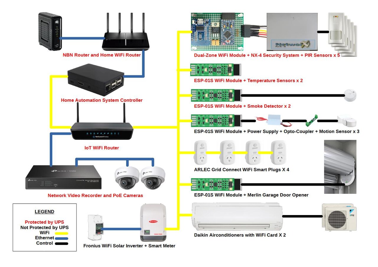
Home WiFi/Ethernet/Internet Router
The home WiFi router provides a Local Area Network over WiFi or Ethernet for our home PCs and mobile devices. It also provides a gateway to the Internet via a hybrid fibre/coaxial cable network.
Home Automation Server
The Home Automation Server is the central hub of the system. It monitors and controls the home IoT devices via the IoT WiFi Router; implements intelligent automation rules; provides a web-based, graphical user interface, over the Home WiFi/Ethernet Router, or over the Internet and broadband mobile network via a secure VPN and, finally, it connects to an SMS gateway (SMS Everyone) providing real-time alerts.
IoT WiFi Router
The IoT WiFi router provides a Local Area Network over WiFi or Ethernet for our home IoT devices. It is completely isolated from the Internet.
Video Surveillance System
The video surveillance system provides CCTV cameras covering different zones of the home, including networked video recording and playback facilities with off-site storage. It connects via the WiFi network.
Solar Inverter and Smart Meter
The solar inverter provides information about the electrical energy being provided by the roof-top solar array and the electrical energy being provided to the home and the grid. It connects to a smart meter via a CAN bus cable. All the information is provided over a WiFi network in XML format using a ReST protocol.
Reverse Cycle Air Conditioner
The reverse cycle air conditioners are used to heat and cool the home. The air conditioning mode (heating, cooling or dehumidifying) and the set temperature can be set over the WiFi network in CSV format using a ReST protocol.
Security System
The security system provides monitoring of passive infrared sensors, an internal screecher, external siren and alerting to an off-site security monitoring centre. To connect it to our IoT WiFi network we had to design an build our own Dual-Zone WiFi Module.
Temperature Sensors
The temperature sensors accurately measure the inside and outside air temperature. They connect via the WiFi network. They comprise our ESP-01S WiFi Module with a Dallas Semiconductor DS18B20 temperature sensor.
Smoke Detectors
The smoke detectors alert to the presence of fire in the home or garage. They connect via the WiFi network. They comprise our ESP-01S WiFi Module connected to the unused I/O pin of the MC145012 chip in a standard home smoke detector.
Motion Sensors
The motion sensors alert us to the presence of visitors entering our property.
Smart Plugs
The smart plugs control the power to various household appliances. They connect via the WiFi network. They are ARLEC Grid Connect units flashed with the ESPHome operating system.
Garage Door Opener
The garage door opener connect to our Merlin MR850 roller door opener. It connects via the WiFi network using our ESP-01S WiFi Module.
Uninterruptible Power Supply
The uninterruptible power supply provides battery backup for all critical systems.
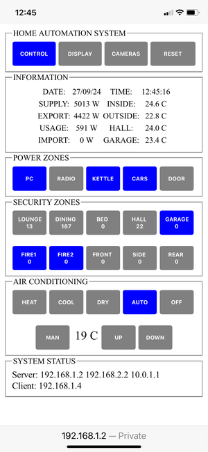
Web Pages
The Home Automation Server includes a Python (Flask/Waitress) web server displaying the following pages. The screenshots show the Control, Display and Cameras page designed to fit our iPhone screens. At the top of each page are a set of page navigation buttons. The blue button indicates the currently selected page.
Control Page
Display Page
Cameras Page
Control Page
The Control page shows Information, Power Zones, Security Zones, Air Conditioning and System Status group boxes.
The Information group box shows: The date and time; solar power generated and exported, home power usage and power imported from the grid; temperatures inside and outside as well as in the hallway and garage.
The Power Zones group box shows: Power indicator/buttons for our PC, radio, kettle, car battery chargers and the garage door opener. Grey indicates the power is off (or the garage door is closed). Blue indicates that the power is on (or the garage door is opened).
The Kettle power zone is an interesting experiment: The kettle (if filled with water and switched on) is programmed to turn on in the morning when the excess solar power exported is greater than 450 W. The 2.4 kW kettle is limited to draw only 400 W using an AC lamp dimmer. This ensures that we can get a morning cup of tea without importing any power from the grid.
The Security Zones group box shows: Alarm indicator/buttons for ten security zones. Grey indicates the zone is not armed, blue indicates the zone is armed. The number displayed below the name indicates the number of times the zone has been triggered since the last time the reset button was pressed. When an armed zone is triggered, an alarm sounds and an SMS message is automatically sent to our iPhones.
The Air Conditioning group box shows: Five modes of operation for our reverse-cycle air conditioning system. Blue indicates the selected mode. The auto mode is an experiment, which turns on the air conditioning in the appropriate mode for the inside and outside temperatures. It advances the temperature setting from the initial ambient value to the final setting by one degree at a time only when the house has achieved the previous increment and only if there is sufficient excess solar power to do so. It turns off the system when there is insufficient solar power. This provides the most efficient heating or cooling by minimising the large initial inrush of energy caused by just manually setting the final desired temperature. To override the auto setting is a manual mode with adjustable temperatures.
The System Status group box shows: The server and client IP addresses.
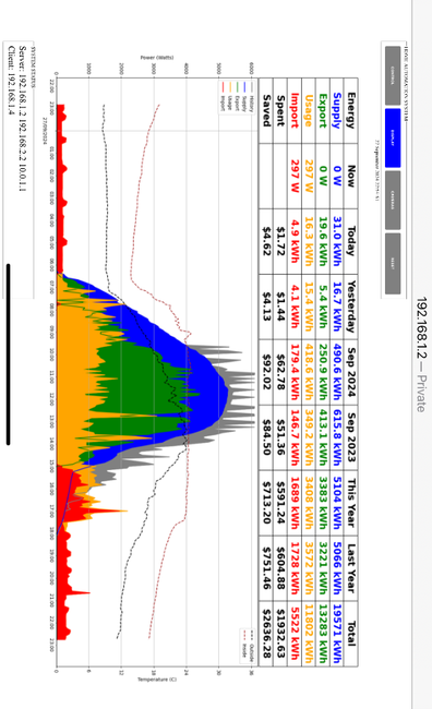
Display Page
The display page shows a table and graph of home automation information intended to permit the assessment of system performance.
The table shows the energy supply, export, usage, import, costs and savings for now, today, yesterday, this month this year, this month last year, this year and last year. All values are prorated to the current date and time.
The graph shows coloured areas for energy supply, export, usage and import over the last 24 hours, together with the history of peak solar supply taken on this day in all previous year. The inside and outside temperatures are also shown as a dotted line.
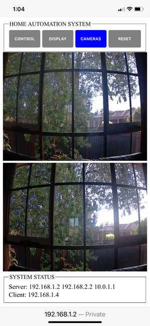
Cameras Page
The Cameras page shows the real-time video and audio (with some latency, of course) from two CCTV cameras. Note: The image was taken before the camera had been properly mounted.
Interfaces
To connect various appliances to our new IoT network we had to design and build several interface modules and use them in various ways:
Dual-Zone WiFi Module
We wanted to connect our home security system, which has 5 Passive Infra-Red (PIR) motion detectors, around the home, to our IoT WiFi network. We have a 4-zone, NX-4 Security System, which is configured for zone-doubling to support up to 8-zones. To achieve this, each zone input can be connected to two sensors, each with a different value End-Of-Line (EOL) resistor. The zone inputs change from being a simple 2-level analog input to being a 4-level analog input. We found that the voltages indicating which sensors are active are actually quite precise. We looked at various Arduino configurations and decided that we would need a 4-channel analog to digital converter, with 4 analog voltage inputs and 8 digital outputs, followed by a WiFi-enabled device with 8 digital inputs. This could not be achieved in one device. A 3.3v 8MHz Atmega328 Pro Mini board was used as the analog to digital converter and a ESP8266 D1-Mini board was used as the WiFi interface. The security system provides a battery-backed 12V power supply. The processor boards have an on-board 3.3V regulator, but to be kind to them, we would feed them from a regulated 5V supply.
Dual-Zone WiFi Module Hardware
The two boards were mounted on a prototyping board with its own 5V regulator:
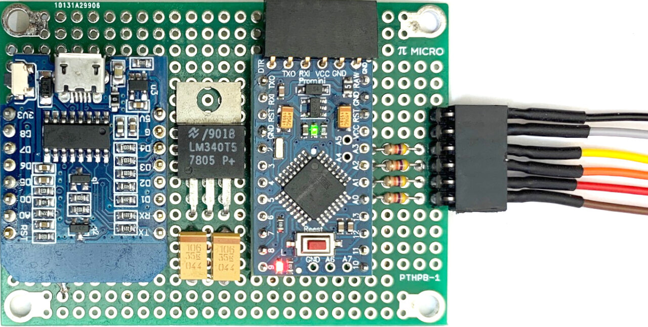
Dual-Zone WiFi Module
The input wires of the Dual-Zone WiFi Module are colour-coded as follows: Brown, red, orange, yellow: Dual-Zone Inputs 1-4. White: 12V. Black: Ground. The Green LED indicates power. The Red LED indicates that one or more zones are active. Annoyingly, the ESP8266 D1-Mini board is also affected by boot-up problems on several of its I/O pins. Hence, only 5 of the 8 digital outputs of the Atmega328 Pro Mini board could be supported. Luckily, in our home, we only have 5 PIR detectors!
Dual-Zone WiFi Module Software
The software for the D1-Mini board was an ESPHome YAML script. The software for the Pro-Mini board was written in C++ with the Arduino IDE. We used the constant declaration area to calculate all the voltages and resistor values required. Here is the code for it:
//These are the characteristics of the security system and its sensors//The security system has 4 physical zones inputs (1-4)const float Ri = 3240.0; //This is the internal pullup resistor, in ohms, on each physical zone in the security system.//In dual-zone mode each physical zone input supports two zones, one low and one high as follows: 1/5, 2/6, 3/7, 4/8//Each sensor comprises a Normally-Closed contact and a series End-Of-Line resistor.const float Rh = 3750.0; //The EOL resistance on the high zone sensor, in ohms.//The high zone is active when Rh is NOT present.const float Rl = 6970.0; //The EOL resistance on the low zone sensor, in ohms.//The low zone is active when Rl is NOT present.const float Rp = 1.0 / (1.0 / Rh + 1.0 / Rl); //The EOL resistance with both sensors inactive, in ohms.const float Vs = 13.55; //The measured security system supply voltage, in volts.//The dual-zone input voltage is Vz//Vz equals Vn, Vh, Vl or Vs, depending on which sensors are active as follows: None, High, Low or Both sensors//Here are the formulas for the dual-zone input voltage in each case, in order of decreasing voltage:const float Vl = Vs * Rl / (Ri + Rl); //Lowconst float Vh = Vs * Rh / (Ri + Rh); //Highconst float Vn = Vs * Rp / (Ri + Rp); //None//To identify active zones we require 3 threshold voltages between Vs & Vl, Vl & Vh and Vh & Vn: Vsl, Vlh and Vhn.//They are:const float Vsl = (Vs + Vl) / 2.0;const float Vlh = (Vl + Vh) / 2.0;const float Vhn = (Vh + Vn) / 2.0;//The active zones can then be tested as follows://Both: if Vz >= Vsl//Low: else if Vz >= Vlh//High: else if Vz >= Vhn//None: Otherwise//The constant K is used to calculate the actual zone input voltage from the analog read value//Given the Arduino supply voltage and the input resistive-divider valuesconst float Vcc = 3.3; //The Arduino Pro Mini supply voltageconst float Amax = 1023.0; //The analogRead values range between 0 and Max for voltages between 0 and Vccconst float R1 = 47000.0; //The chosen voltage divider resistor connected to the zone inputconst float R2a = R1 / (Vs / Vcc - 1); //Calculate the required voltage divider resistor connected to ground (= 15132)const float R2 = 15000.0; //The chosen voltage divider resistor connected to groundconst float Vmax = Vcc * (R1 + R2) / R2; //The maximum permitted zone input voltageconst float K = Vmax / Amax; //A constant to convert analogRead values to zone input voltage
System Characteristics:Ri: 3240Rh: 3750Rl: 6970Rp: 2438Vs: 13.55Vl: 9.25Vh: 7.27Vn: 5.82Vsl: 11.40Vlh: 8.26Vhn: 6.54Vcc: 3.30Amax: 1023R1: 47000R2a: 15132R2: 15000Vmax: 13.64K: 0.0133
ESP-01S WiFi Module
We wanted to connect some temperature sensors, smoke detectors, motion sensors and a garage door opener to our IoT WiFi network. The natural solution was to use these tiny, cheap ESP-01S Espressif 8266 breakout boards. These have an ESP8266 processor, 1MB of RAM and a WiFi interface on board.
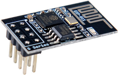
Esspressif ESP-01S Breakout Board
These ESP-01S breakout boards have 4, 3.3V, General Purpose Input/Output (GPIO) pins. However, since we needed to connect real-world devices like a 12V power supply, a 12V switch input, a 12V relay output and a DS18B20 one-wire temperature sensor, we had to design and build our own ESP-01S WiFi Module to mount the ESP-01S breakout board together with extra interface components.
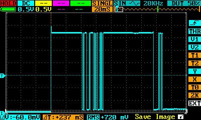
ESP-01S Boot-Up Investigation
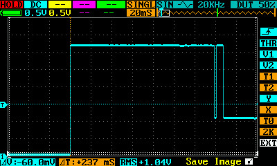
One drawback with the ESP-01S breakout board is that the only available GPIO pins can be quite temperamental when the device is booting up. Some GPIO pins pulse high or low for up to 150ms and some can't be pulled low while booting (and some do both). So deciding which GPIO pins to use can be quite a challenge. Most users encounter these problems and simply apply workarounds using heavy filter capacitors on the GPIO pins. This is not an appropriate solution, of course.
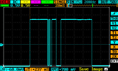
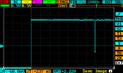
To fully investigate the situation, we provided a 4k7 Ohm pull-up resistor on GPIO pins 0 to 3. We set each pin as a non-inverting output and alternately set the output high and low after boot up at the earliest possible opportunity. This was to discover the full extent of the boot-up waveforms. For those interested in the ESPHome YAML configuration, this is done using an on_boot event in the esphome section and turning on or off the outputs at a priority level of 600 - just after the GPIO pins are configured. In all cases the output waveform did not stabilise for 150ms after boot. Here are the boot-up waveforms that we recorded:
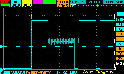
GPIO 0 Set High and Low After Boot
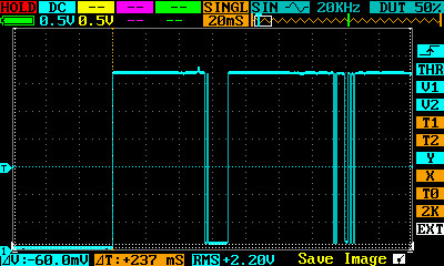
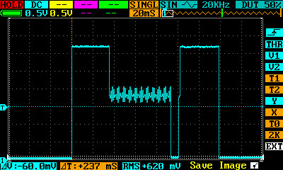
GPIO 1 Set High and Low After Boot
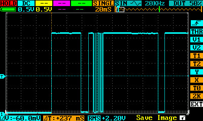
GPIO 2 Set High and Low After Boot
GPIO 3 Set High and Low After Boot
ESP-01S Pin Usage
Here are our design decisions:
- GPIO3 is unusable as an output as the low level was above 1V, but it is the only pin that can be low on boot. So we used it as an input.
- GPIO2 can be used as an I/O pin for the DS18B20 one-wire bus, or as SCL for an I2C bus, but must be pulled high on boot.
- GPIO1 is not needed in our design, but must be pulled high on boot. It can be used as SDA for an I2C bus in conjunction with GPIO2, and in hindsight we should have provided a separate pad for it. The pad for pin 2 of R2 can be used instead.
- GPIO0 can be used as an output, but only with a properly designed Low Pass Filter (LPF) to stop the boot-up pulses propagating to the output, and it must be pulled high on boot.
ESP-01S WiFi Module Schematic Diagram
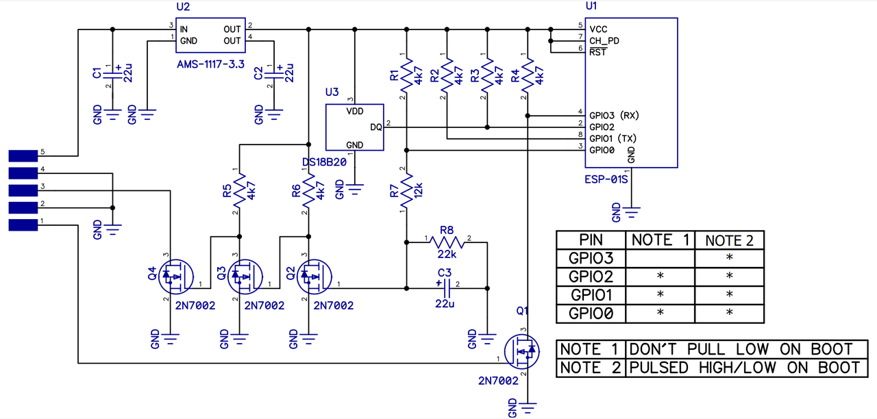
Here is the schematic diagram of our ESP-01S WiFi Module. U1 is the ESP-01S with 4 I/O pins, GPIO 0 - 4. U2 is a 3.3V regulator, which can handle up to 15V input. U3 is a Dallas Semiconductor DS18B20 one-wire temperature sensor. R1 - R4 are pull-up resistors on all I/O pins. Q1 is an input MOSFET, which can handle up to +/- 20V on its gate. Q2 is the LPF in conjunction with R7, R8 and C3. Q3 is an inverter, Q4 is an output, which can handle up to 60V at 115mA.
ESP-01S Module Schematic Diagram
ESP-01S WiFi Module LT Spice Simulation
To ensure the Low Pass Filter worked well under all conditions we used LT Spice to model and simulate its operation. Here is the LT Spice schematic: The GPIO provides 3.3V pulses. A 12V external supply is connected to Q3 via a 120 Ohm resistor, limiting the current to 100mA. We designed the LPF to remove up to 230ms of input pulses - a 50% margin on our measurements.
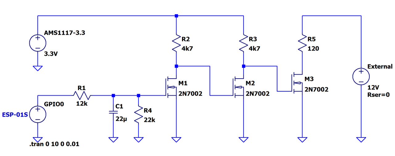
LT Spice Schematic of the Low Pass Filter output circuit
The LT Spice simulation is shown below. The GPIO waveform is shown in green. The output waveform is shown in blue. A 3.3V 230ms GPIO pulse is generated at 1s to simulate the boot-up pulse. A 3.3V 1s GPIO pulse is generated at 2s to simulate a normal GPIO output waveform. We can see that the 230ms pulse at boot-up does not propagate to the output, while the normal GPIO output does, except that it is shortened by about 230mS, which is OK. The main usage of this output circuit is to pulse a garage door opener, for about 1s, while making sure that the garage door is not operated at boot up.
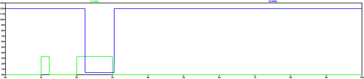
LT Spice Simulation of the Low Pass Filter output circuit
ESP-01S WiFi Module Printed Circuit Board
The PCB top-view is shown below. The ESP-01S is mounted on the bottom side of the PCB.
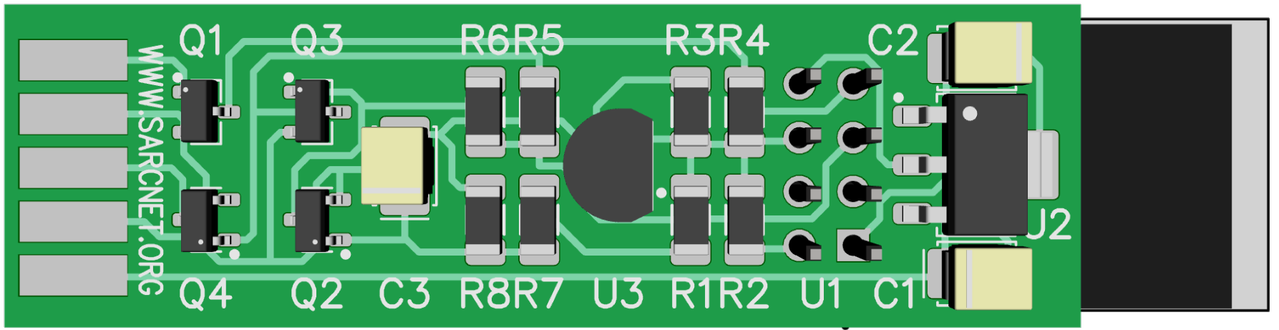
ESP-01S WiFi Module Top View
The PCB side-view is shown below. In practice the plastic spacer on the header is removed and the ESP-01S is mounted flush. Depending on the application, some of the components may be optional.

ESP-01S WiFi Module Side View
ESP-01S WiFi Module Software
The ESP-01S WiFi Module was programmed using ESPHome YAML script.
Smoke Detector WiFi Interface Module
We wanted to connect two smoke detectors to our IoT WiFi network. These detectors are very basic, 9V battery-powered models. Internally, they use a MC145012 chip which, according to the data sheet, is a "Photoelectric Smoke Detector IC with I/O and Temporal Pattern Horn Driver". Importantly, pin 7 is a 9V, Input/Output pin, allowing multiple smoke detectors to be daisy-chained together. It is pulled to 9V when smoke is detected. We carefully opened the unit and removed the photo-electronic smoke detector module. We soldered two fine wires to MC145012 pin 7 I/O and pin 14 GND, using dobs of hot-melt glue to secure the wires. Reassembling the unit, we soldered the other ends of the fine wires to our ESP-01S WiFi interface module, which conveniently fitted inside the case above the 9V battery compartment. This module only needed the components for a digital input. As the input device is 2N7002 MOSFET there would be no loading on the MC145012 I/O pin. The unit was powered from the battery-backed 12V power supply from our DAS NX4 security system.
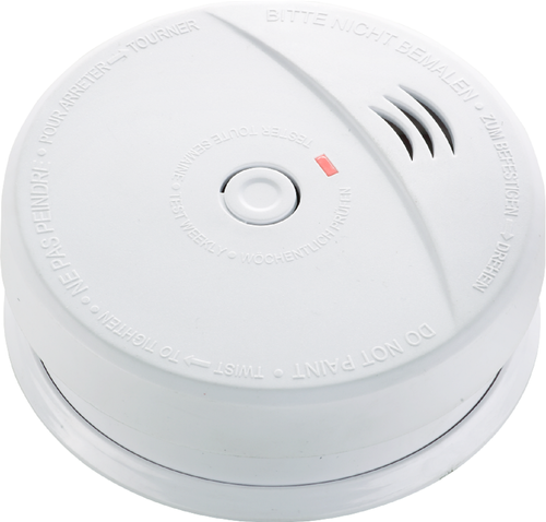
Basic 9V Battery-Powered Smoke Detector
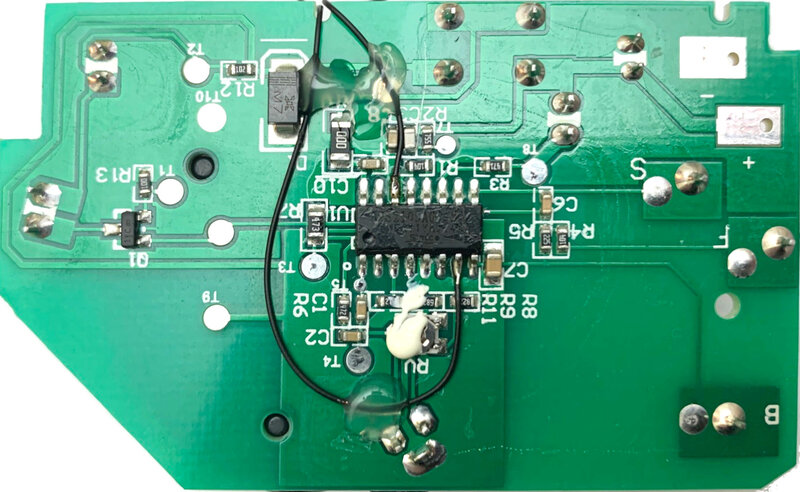
Underside of the Photo-electronic Smoke Detector Module showing soldered wires
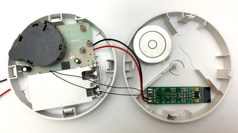
Assembly of the unit with our ESP-01S WiFi Interface Module
Problems:
Later, we decided to add a Dallas Semiconductor DS18B20 temperature sensor to the ESP-01S WiFi interface module - it would then detect smoke and heat! The sensor was mounted at the end of a short cable, hanging down from the smoke detector case. It was then we found a significant design problem: The AMS-1117 3.3V regulator on the ESP-01S WiFi interface module gets pretty hot with the module running on 12V. It dissipates nearly 1 Watt! Unfortunately the heat affects the reading of the nearby temperature sensor. The alternative solutions were to mount the sensor on a longer chord or to run the ESP-01S WiFi interface module off a 5V regulated supply. We decided on the latter, equipping the affected security system zones with an in-line 5V regulator. Problem solved.
Motion Sensor WiFi Interface
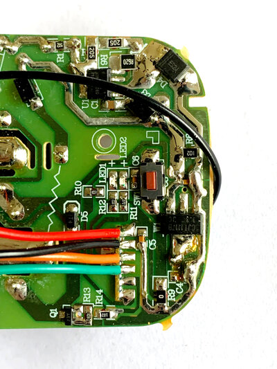
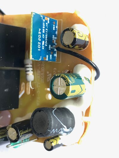
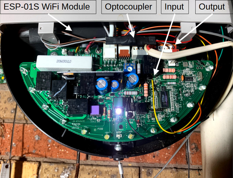
We wanted to connect three microwave (Doppler) motion sensors to our IoT WiFi network. We reused our ESP-01S WiFi module to connect the sensors to our home automation system. However the sensors were AC mains powered with a AC mains output normally used to control a lamp. The interface therefore required an optocoupler to isolate the sensor output from the input of the ESP-01S WiFi module. The ESP-01S WiFi module also required a 5V DC mains power supply.
ARLEC Grid Connect Smart Plug WiFi Interface
We wanted to connect four ARLEC Grid Connect Smart Plugs to our IoT WiFi network. Unfortunately, when purchased, these units only work with a cloud-based app, so we had to reprogram them with the ESPHome operating system. The hardest part of doing that was opening the plastic case. It required an uncommon, tri-star, security bit tool. We managed to find one on eBay. We opened the case, undid a few more, normal, Phillips screws and removed the circuit board.
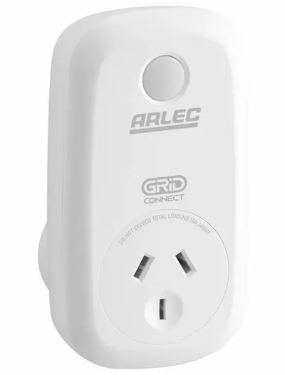

ARLEC Grid Connect Smart Plug and Special Tri-Star Driver
To reprogram the device we used a USB 3.3V to Serial converter. We first soldered coloured wires to a SIP socket that fitted on to the converter pins. The colours used were: Red - 3.3V; Black - Ground (2-wires); Orange TXD and Green RXD.
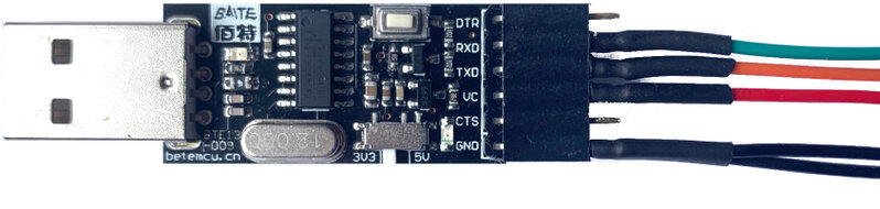
USB to 3.3V Serial Converter
We then noted the connections of the TYWES module and soldered the other end of the coloured wires to it
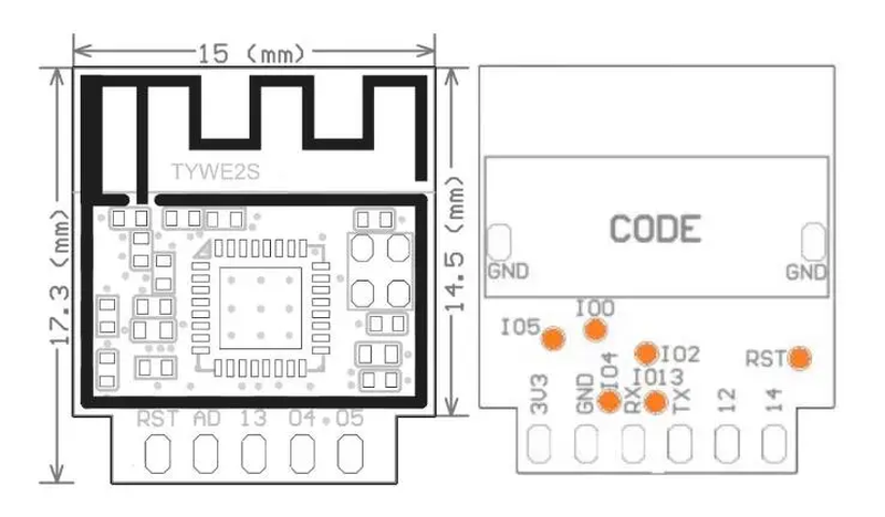
TYWE2S ESP8266 WiFi Module
Four of the coloured wires soldered easily to the edge connector of the TYWE2S module, noting that the TXD and RXD wires had to be cross-connected. However one black ground wire had to be soldered to the I00 pad on the bottom side of the module. This wire was to hold the TYWE2S module into programming mode.
Soldering USB 3.3V Serial Converter Wires to TYWE2S
The USB to Serial converter was then connected to the Raspberry Pi and an ESPHome command (e.g. esphome -s zone 0 -s ip_address 192.168.2.6 run plug.yaml) was used to program it using the YAML configuration file shown here. When USB programming was complete, the programming ground wire was unsoldered from the TYWE2S module and the USB power was cycled to permit a normal boot up. Once the unit booted up, an ESPHome command was used to test OTA programming. Once that was confirmed, all the coloured wires were unsoldered from the TYWE2S module and the circuit board was replaced in the case (with those super-secure screws to prevent further tampering).
Garage Door Opener WiFi Interface Module
We wanted to connect our Merlin MR850 garage door opener to our IoT WiFi network. However using our ESP-01S WiFi Interface Module required some additional interface circuitry. The reason is that the MR850 runs on around 33V DC and all I/O signals share that voltage. The MR850 output was 33V when the door was open. The MR850 input had to be connected to 33V, momentarily, to open or close the door. Unfortunately, the 2N7002 input MOSFET on our ESP-01S WiFi Interface Module only handles +/- 20V on the gate. And the 2N7002 output MOSFET on our ESP-01S WiFi Interface Module is active-low and pulls the output to ground, not to 33V. So we added a voltage divider on the input and an LH1510 optocoupler on the output.
Garage Door Opener Modifications
Programming
We used an old Raspberry Pi Model 3B as our Home Automation Server. It runs a Mosquitto MQTT broker so that our server and all of our IoT devices can publish and subscribe messages without having to know individual IP addresses. We used the Raspberry Pi to program the ESP-01S WiFi Modules with ESPHome. We then created Python scripts, the main one running as a service on the Raspberry Pi, to gather data and apply home automation rules. A brief sketch of the process is as follows:
Raspberry Pi configuration
Starting with a fresh install of the Raspberry Pi OS with desktop, open a terminal window and run the following commands (you can copy and past them into a terminal window)
#Install the Python IDE and the MQTT broker
sudo apt update
sudo apt -y full-upgrade idle3 mosquitto
#These days Python must run in a virtual environment so that each user gets their own Python libraries
#The virtual environment has to be activated before each use
#When activated, the Linux prompt then changes from:
#<username>@home:~ $ to (env) <username>@home:~ $
#Create a virtual environment for Python called env in your /home/<username> directory
cd ~
python3 -m venv env
#Activate the virtual environment. Use source to ensure environment variables are persistent.
source ~/env/bin/activate
#Now install the latest version of PIP and the required python libraries into your virtual environment
pip3 install --upgrade pip paho-mqtt esphome
#Configure the Python Idle3 shortcut to auto-activate the Python virtual environment
#Click Raspberry | Programming
#Right Click IDLE (using Python-3.11)
#Click Properties | Desktop Entry
#Enter /home/<username>/env/bin/python3.11 -m idlelib.idle
#You no longer have to activate the virtual environment if you run Python Idle3
#The following commands need to be executed as root, so now you become root
sudo -i
#Create the MQTT Broker mosquitto.conf file
#This command puts the following lines, up to EOF, into the file
cat > etc/mosquitto/mosquitto.conf << EOF
# Place your local configuration in /etc/mosquitto/conf.d/
#
# A full description of the configuration file is at
# /usr/share/doc/mosquitto/examples/mosquitto.conf.example
pid_file /run/mosquitto/mosquitto.pid
persistence true
persistence_location /var/lib/mosquitto/
log_dest file /var/log/mosquitto/mosquitto.log
include_dir /etc/mosquitto/conf.d
listener 1883
allow_anonymous true
EOF
#Start the mosquitto service
systemctl restart mosquitto
#To test MQTT:
#Open a new terminal window for the subscriber
mosquitto_sub -h localhost -p 1883 -t MyTopic
#Open a second terminal window for the publisher
mosquitto_pub -h localhost -p 1883 -t MyTopic -m Hello World
#Hello World should appear in the subscriber window
ESP-01S WiFi Module Programming
ESPHome is an operating system for the ESP-01S (ESP8266 breakout board), and others. It is configured with a YAML file, is compiled and uploaded to the board over the air (Except initially, which must be done via a USB-Serial converter). It boots up the CPU, processes sensors and allows communications via WiFi.
Here is an example ESPHome YAML configuration file for separate ESP-01S WiFI Modules used as inside and outside temperature sensors. They work via an MQTT broker running on the Raspberry Pi. We use simple MQTT topics aligned with the home automation server. E.g. The server subscribes to topic 's15' to read the inside air temperature, which is sent automatically every 60 seconds. The server publishes a '?' message to topic 'p15' to request a update to the the inside air temperature. Here is the ESPHome temp.yaml file:
#This ESPHome temp.yaml file configures a black ESP-01S board fitted 1MB ram and a Dallas DS18B20 temperature sensor
#The temperature sensor is connected via the one-wire bus to GPIO02
#One sensor is for Inside Air Temperatire (IAT) and the other is for Outside Air Temperature (OAT)
#To upload the IAT sensor set the name, zone and IP address of the ESP-01S WiFI Module: esphome -s name iat -s zone 15 -s ip_address 192.168.2.17 run temp.yaml
#To upload the OAT sensor set the name, zone and IP address of the ESP-01S WiFI Module: esphome -s name oat -s zone 16 -s ip_address 192.168.2.18 run temp.yaml
#Set up constants
substitutions:
name: 'iat' #The name of this device
zone: '15' #IAT topic
# name: 'oat' #The name of this deviceip_address: '192.168.2.17' #Static IP address of this device
# ip_address: '192.168.2.18' #Static IP address of this device
# zone: '16' #OAT topic
from_server: 'p${zone}' #The topic for receiving messages from the serverto_server: 's${zone}' #The topic for sending messages to the serverstate_message: '?'
#Set up core functionality
esphome:
name: ${name} #The name of this devicecompile_process_limit: 2 #Reduce the number of cores to use. Necessary for compiling on the RPi 3.
#Set up processor and board
board: esp01_1m #The Black ESP-01 board with 1MB of ram
#Set up WiFi
wifi:
ssid: A #This network is isolated from the Internet, but has an MQTT brokerpassword: <SECRET>manual_ip:static_ip: ${ip_address}gateway: 192.168.2.1subnet: 255.255.255.0
#Enable a fallback access point in case the WiFi connection fails
ap:
ssid: ${name} #Use the device name as the SSID
#Enable the captive portal for the WiFi access point
captive_portal:
#Enable logging
logger:logs:mqtt.component: DEBUG
#Enable programming Over The Air
ota:
- platform: esphome
#Enable Message Queuing Telemetry Transport
mqtt:
broker: 192.168.2.2 #The IP Address of the MQTT brokerport: 1883 #The port number of the MQTT brokeron_message: #When a message is received from the MQTT broker
- topic: ${from_server} #When a message is received from the serverpayload: ${state_message} #When a state message is receivedthen:
mqtt.publish: #Publish an MQTT message
topic: ${to_server} #Publish a message to the serverpayload: !lambda |-
return to_string(id(temp).state);
one_wire:
- platform: gpiopin: GPIO02
sensor:
- platform: dallas_tempid: tempaddress: 0x0200000042495a28update_interval: 60son_value:
then:mqtt.publish: #Publish an MQTT message
topic: ${to_server} #Publish a message to the serverpayload: !lambda |-
return to_string(id(temp).state);
Home Automation System Programming
Our Raspberry Pi Home Automation Server is programmed in Python 3. Suffice to say that the scripts subscribe to ESP-01S WiFI Modules, used as sensors, apply home automation rules to the data received and then publish commands to ESP-01S WiFI Modules, or other devices, used to control home appliances. Of course this is all integrated with a Python web server (not described here). The heart to the process is an MQTT library shown below. All you have to do is initialise it and point it to your own callback function to process subscribed topics.
#Home automation system MQTT class library
#Copyright (c) 2024, Julie VK3FOWL and Joe VK3YSP.
#For The School Amater Radio Club Network (r) VK3SRC.
#This program:
# Implements a Message Queuing Telemetry Transport (MQTT) client
# Subscribes to WiFi sensor topics
import paho.mqtt.client as mqtt
class Mqtt(object):
def __init__(self, host, port, callback):
#Constructor
#self.client = mqtt.Client(mqtt.CallbackAPIVersion.VERSION2) #Create an mqtt client
self.client = mqtt.Client() #Create an mqtt client
self.client.on_message = callback #Assign a message handler
if (self.client.connect(host, port, 60) == 0): #Connect to the mqtt broker
print('Connected to MQTT broker')
self.client.loop_start() #Start handling mqtt messages
print('MQTT client started')
def subscribe(self, topic):
#Subscribe to an mqtt topic
self.client.subscribe(topic)
def publish(self, topic, message):
#Subscribe to an mqtt topic
self.client.publish(topic, message)
if __name__ == '__main__':
#Test script
def mqttCallback(client, userdata, message):
print(f'MQTT: {message.topic}: {message.payload.decode()}')
mqttIP = 'localhost'
mqttPort = 1883
mqtt = Mqtt(mqttIP, mqttPort, mqttCallback)
mqtt.subscribe('Test1')
mqtt.subscribe('Test2')
mqtt.publish('Test1','Message1')
mqtt.publish('Test2','message2')