Robotics Platform - SARCBOT2
Note: This page is currently under development since 1 March 2020.
This project is a robotics platform designed to help students learn about robotics and to build their own robot. It builds on the knowledge gained from the design and development of SARCBOT1. Like its predecessor, SARCBOT2 is a rover with the capabilities of both remote control and autonomous operation. The main areas of improvement are:
- A vehicle platform which moves well on different home flooring surfaces like carpet and tiles.
- Synchronisation of the right and left drives to maintain a straight heading
- Accurate control of vehicle speed over different surfaces
- Accurate odometer measurement
- Accurate location of surrounding walls and obstacles
- Accurate heading determination and control
Design and Development
The design and development of SARCBOT 2 is documented in the following sections:
SARCBOT2 follows the design and development phases described in our Robotics Workshop Plan:
Phase 1: Power and Drive SubsystemsPhase 2: Sensor SubsystemsPhase 3: Actuator SubsystemsPhase 4: Control SubsystemsPhase 5: Communication SubsystemsPhase 6: Navigation SubsystemsPhase 7: Robot applications
System Requirements
The system shall comprise a rover segment and a remote segment.
The system shall have a remote control mode and an autonomous mode.
The remote segment shall be capable of switching the system between remote control mode and autonomous mode.
The remote segment shall be powered by mains power.
The rover shall be powered by rechrageable batteries.
The rover shall work on domestic floor surfaces, such as tiles and carpet, without slipping.
The rover heading and speed shall be controlled by the remote segment in remote control mode.
The rover heading and speed shall be controlled autonomously in autonomous mode.
The rover heading and speed shall change between stationary, slow, fast, forward and reverse, straight, right or left, smoothly.
The rover shall be capable of moving forward or backward in a straight line.
The rover shall be capable of turning to the right or to left while moving forward or reverse.
The rover shall be capable of turning to the right or to the left, in a complete circle, while stationary.
Concept of Operation
Design Decisions
The following design decision were made to meet the system requirements.
Tracked Vehicle Platform
To improve traction over household floor surfaces, SARCBOT2 is based on a Tracked Vehicle Platform. This platform differs from SARCBOT1 with its four independently driven wheels. The tracked platform has an overall measurement of 18cm wide, 18cm long and 6cm high. It has two independent geared DC motors Model: 33GB-520-18.7 rated at 12VDC, 350RPM
Modular Equipment Enclosures
Suspended between the catapillar tracks is a chassis suitable for mounting equipment, measuring 8cm wide, 14cm long and 4cm high. In an attempt at modularisation and facillitating interchangeability of subsystems, it was decided to enclose the electronics in stackable Sistema containers, in both 200ml and 400ml sizes. These containers measuring 9cm wide by 11cm long, which each have seals and clips to keep them closed, can be mounted to the chassis and stacked togther using M3x10mm countersunk machine screws. They are large enough to fit a 12V rechargable battery pack or even a Raspberry Pi computer. To minimise the centre of gravity, the number of interconnections between modules and the field of view of the sensors, the following stacking order was decided:
TopSensor ArrayMicrocontrollerMotor DriverBattery PackBottom
Power and Drive Subsystems
Sensor Subsystems
Actuator Subsystems
Control Subsystems
Navigation Subsystems
Communication Subsystems
Robot Applications
Hardware Reference
The platform is based on an inexpensive ($40) tracked robot tank platform, including the following parts:
- Tracked Vehicle Platform (Tracked Robot Tank Platform)
- Microcontroller (Arduino Pro Micro 5V/16MHz)
- Wheel Sensor (TCRT5000 Infrared Line Track Sensor)
- Wide Beam Obstacle Sensor (HC-SR04 Ultrasonic Distance Sensor)
- Narrow Beam Obstacle Sensor (VL53L0XV2 Time-Of-Flight Laser Sensor)
- Motor Driver (L298N Dual Channel Motor Driver)
- Miscellaneous cables, mounting hardware and fasteners as required
- The vehicle kit and other items were all purchased on eBay. You can find them by searching eBay with the titles in parentheses above.
Tracked Vehicle Platform

The Tracked Vehicle Platform

The Tracked Robot Tank Platform (DIY Kit of Parts)
Microcontroller
Wheel Sensor
Wide Beam Obstacle Sensor
The HC-SR04 Ultrasonic Distance Sensor
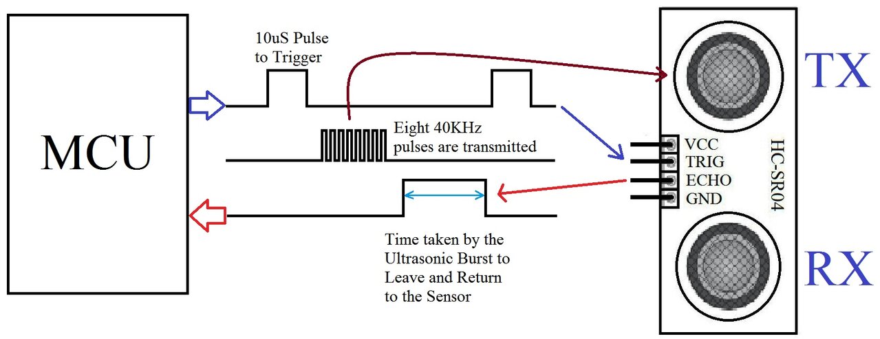
The HC-SR04 Ultrasonic Distance Sensor waveforms
After a 10us trigger pulse to the TRIG input, the sensor emits eight (8) ultrasonic pulses at 40kHz. The resultant pulse width of the echo output signals the distance to the nearest target. The maximum echo pulse width of 36ms indicates no target was found.
Narrow Beam Obstacle Sensor
Motor Driver

The L298N Motor Driver Board
Note: The kit only contains one L298N Motor Driver Board. The motors on each side of the car are connected in parallel.
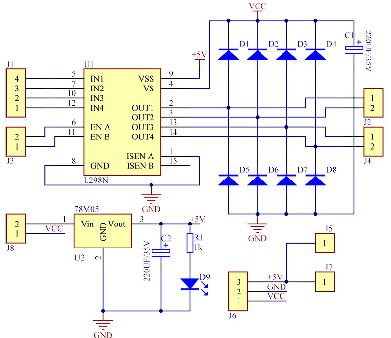
The L298N Motor Driver Board schematic
The driver has 4 independent outputs. To control a motor in the forward and reverse direction, two outputs are required per motor. Hence, one L298N Motor Driver Board can drive two motors.
Miscellaneous