
Electronic Kit Construction
Constructing electronics kits is fun. Your electronics kit contains all the electronic components you need, the circuit schematic diagram which shows how the components are connected together and step-by-step instructions for assembling it yourself. Of course you will also need your own tools like a soldering iron and wire cutters - but more on that later.
Actually, there are many different ways of building an electronic circuit. You can build it by simply plugging the electronic components into a solderless IC socket or "breadboard" and then using "jumper" wires to connect it up. While this is not a very permanent solution, it is quick, doesn't require any solder and it gives you a chance to see the circuit working and adjust any component values. This step is called "prototyping" and is a good idea if you are not sure if a circuit will actually work first time.
Another way to build a circuit is to just solder all the components together in "mid air" making a circuit that looks like a 3D sculpture. It may work, but it is a very delicate structure. Any slight movement could break a wire or short-circuit the battery - so not so good!
However, the best way to build a permanent electronic circuit is to use a Printed Circuit Board or PCB. You mount your component leads through holes in the PCB then permanently solder them on the other side. The PCB has wires "printed" on it to connect your components together in a circuit. The PCB is made out of fibreglass. The wires are called "tracks" and they are actually etched from a solid piece of thin copper foil stuck to the board. You solder your component leads to copper "pads" surrounding the holes.

Introduction
WARNING: This kit contains a battery. Connecting the red and black leads of the battery together may cause the battery or wires to get hot. Your supervisor will only provide the battery when your circuit has been checked.
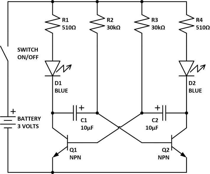
Circuit schematic
A circuit is a collection of electronic components connected together to perform a function using electric current. A circuit schematic is a diagram (like a map) showing how all the components are connected. The components are drawn as stick-figures or "circuit symbols". The circuit symbols for our components are described in our electronic component activity.
In a circuit schematic, lines represent wires connecting the leads of components together. A dot where wires cross indicates that the wires are connected. A bump where wires cross indicates that the wires are not connected. Components are numbered when more than one of each type of component is used. Resistors are numbered R1, R2 etc. Capacitors C1, C2 etc. Diodes D1, D2 etc. And transistors Q1, Q2 etc. The number and value of the component are shown next to the component circuit symbol.
How It Works
Referring to the circuit schematic above. When the electric current from the battery is turned on using the switch, this circuit makes two Light Emitting Diodes (LEDs) flash on and off alternately at a certain rate. But how does it actually work? Let's take it step-by-step:
- When the switch is off there is no electric current flowing in the circuit. It is completely dead. Both LEDs are off. Boring!
- Now complete the circuit by turning on the switch. The chemicals in the battery generate electric current and it flows through the circuit.
- Electric current flows like a waterfall from the top of the circuit to the bottom, from the positive (+) terminal of the battery down through to the negative terminal.
- Initially, the transistors Q1 and Q2 are both off, so no current flows down through the top of the transistors. So no current flows through R1 & D1 or R4 & D2. So at this stage the LEDs are still off. But just wait.
- A small electric current does flow through R2 and R3 into the middle of Q1 and Q2 and when that happens the transistors will turn on.
- Initially it is a race to see which transistor will turn on first! And because electronic components are very slightly different, one of them will always win. Lets say that Q1 wins the race and it turns on first before Q2.
- When Q1 turns on electric current surges through R1, D1 and Q1 in the direction of the arrows, tuning on the bright blue LED, D1.
- Luckily resistor R1 reduces the electric current to a safe operating level for D1 and Q1, otherwise they would be damaged.
- When Q1 first turns on, capacitor C1 is completely discharged so all the electric current flowing through R2 goes to charge up C1 and it does not flow into the middle of Q2. Making sure that Q2 and its LED, D2 are both off.
- But tuning on Q1 also makes C1 start charging up through R2. This takes a little time depending on the values of R2 and C1.
- When C1 is charged up electric current stops flowing into C1 and starts to flowing into the middle of Q2. All of a sudden Q2 turns on and by the same mechanism above, Q1 is automatically turned off.
- When Q2 turns on electric current surges through R4, D2 and Q2 in the direction of the arrows, tuning on the bright blue LED, D2.
- Sound familiar? You guessed it. This process repeats over and over, all the while flashing the LEDs on and off.
- This is actually a famous circuit called an "astable multivibrator". You can build one for yourself and watch it work!
Breadboard assembly
The electronic components are plugged into a breadboard so that the circuit can be tested before permanent assembly onto a PCB. The breadboard shown above has 17 rows of sockets divided into two sides. The sockets on the left side are not connected to the sockets on the right side. But the sockets in each row are connected together. That is row 1 columns a, b, c, d and e are connected together and row 1 columns f, g, h, i and j are also connected together, and so on for each row.

In this instance, the component placement was chosen to resemble the circuit diagram. While the orientation of the resistors is not critical, it is customary to arrange their colour codes in the same direction. The orientation of the LEDs, capacitors and NPN transistors is critical and was determined by reading the component markings or consulting the datasheet. Reversing these components could damage them. Here are some clues: The longest leg of the LEDs is the positive side. The capacitor has a stripe on the body to indicate the negative side.
Start assembly in the centre of the breadboard and work your way outwards. Bend the resistor leads in a smooth curve ending at right angles to the body. Use tweezers to insert the resistor leads as they are easily bent.
- Insert the four jumper wires first
- Insert the NPN transistors
- Insert the 30k ohm resistors
- Insert the capacitors
- Insert the 510 ohm resistors
- insert the LEDs
- Trace out the circuit to be sure there are no wrong connections
- Get your supervisor to check the circuit
- Connect the red and black battery wires as shown.
- Turn on the switch. If the circuit does not work go back to step 7.
Printed Circuit Board assembly
Once the prototype is working, you can remove the electronic components from the breadboard and reuse them in a real PCB electronic kit. For details see our electronic kit construction booklet.
Preparation
You will need:
- Electronics kit components for each student, including PCB, batteries and battery holder
- One (1) solderless IC socket (breadboard) for each student
- Four (4) Jumper wires for each student
- A printout of our electronic kit construction booklet for each student.
- Tools and safety equipment specified in the booklet.
Activity
- Assemble the kit on a breadboard.
- Have your supervisor check your layout and provide the battery.
- Turn it on and test it.
- Read and understand about how it works above.
- Remove the components from the breadboard and assemble the components onto a PCB: Step by step instruction for assembling this kit on a PCB and using it to make a working model are given in our electronic kit construction booklet.

Homework
- Play I-spy with electronic devices: E.G. "I-spy with my little eye something that beeps".
- Electronics devices are everywhere. You don't believe it? Then test yourself: See if you can spend 5 minutes without watching, hearing, smelling, feeling or tasting an electronic device or its products.