SARCNET Motor Control

Published by Julie & Joe in Robotics · Saturday 24 Aug 2019
In 2018, SARCNET was running a prototyping workshop, for graduates of our School Amateur Radio Clubs, on Tuesday nights 6-8pm at Moorabbin and District Radio Club. The workshops are no longer running pending a new batch of students and possibly a new venue, such as a public library. For more details see our workshops page.
This forum is for anyone wanting to read about our robot building experiences and to add their own comments or to ask questions.
We started with a 4WD car kit, purchased on eBay for around $30, as shown above. Of course, we were never going to follow the original design! We were going to use it to design and build SARCBOT as a group. Then were then going to modify that design for our own robots, which we could call MYBOT or JULIEBOT etc. Our first challenge with this robot was to drive the four DC motors. Since the Arduino does not have enough current drive capacity to power DC motors directly, we connected the motors via a L298N controller board, provided with the kit, as follows:

•The two red wires of the right motors were connected to OUT1
•The two black wires of the right motors were connected to OUT2
•The two red wires of the left motors were connected to OUT3
•The two black wires of the left motors were connected to OUT4
•The L298N inputs IN1, IN2, IN3 and IN4 were connected to Arduino Pro Micro PWM output pins 9, 6, 5 and 3 respectively
•The Arduino VCC and GND pins were connected to +5V and GND respectively
•A six (6) volt battery was connected to +12V and GND
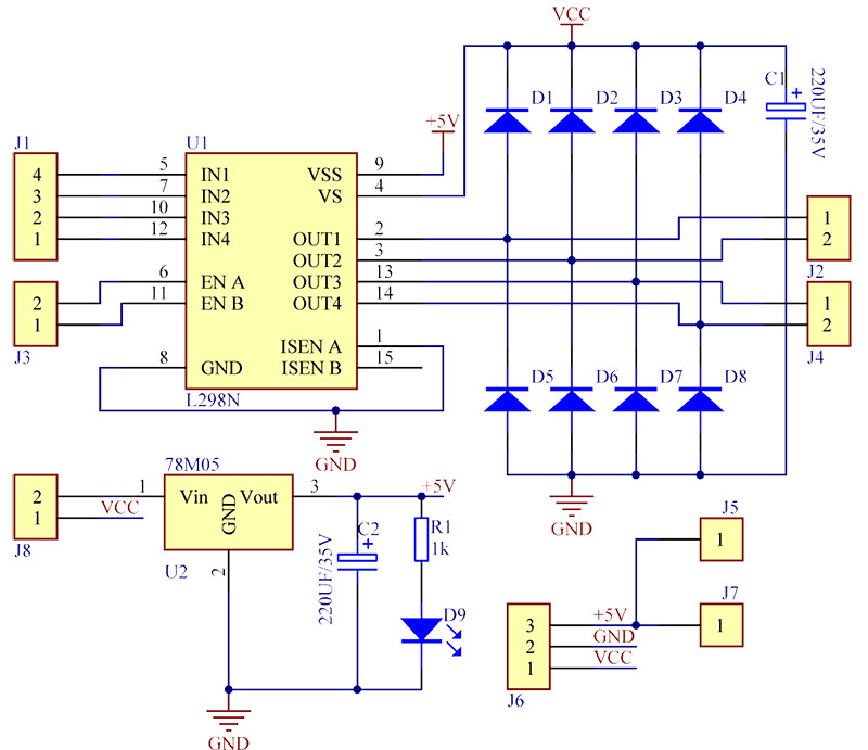
Here is the circuit schematic of the L298N driver board. Each of the outputs can be driven HIGH (6 volts) or LOW (GND). There is also a handy 5V regulator on the board which can power the Arduino, stand-alone, off the 6V battery.
The following code was used to test the basic motor-drive system. The motors all came on full speed forward for 2 seconds and then full speed reverse for seconds. All motors worked, but the platform lurched each time it changed direction. Our next experiment will be to produce smoother starting and stopping.
//Basic ON/OFF motor control
//Declare the Arduino PWM pins
const int pwm1 = 9;const int pwm2 = 6;const int pwm3 = 5;const int pwm4 = 3;
void setup() {
//Set the pin's mode to OUTPUTpinMode(pwm1, OUTPUT);pinMode(pwm2, OUTPUT);pinMode(pwm3, OUTPUT);pinMode(pwm4, OUTPUT);
}
void loop() {
//Drive all motors forward
digitalWrite(pwm1, 1);
digitalWrite(pwm2, 0);
digitalWrite(pwm3, 1);
digitalWrite(pwm4, 0);
delay(2000);
//Drive all motors reverse
digitalWrite(pwm1, 0);
digitalWrite(pwm2, 1);
digitalWrite(pwm3, 0);
digitalWrite(pwm4, 1);
delay(2000);
}
Our first motor control test was a success, but we noticed that our robotics platform would jerk every time the motors changed direction. So we needed to control the motors more smoothly. Instead of turning the motors full on and full off, we needed to turn them on and off gradually. So we decided to use Pulse Width Modulation (PWM).
Digital Input/Output (DIO) pins on the Arduino are just ON or OFF, HIGH or LOW, 1 or 0, +5V or GND. It can't help but make the motors jump. PWM, on the other hand, is an easy way to cause a more gradual starting and stopping of the motors. A PWM output pin on the Arduino is not just ON or OFF, it pulses ON and OFF so fast that the motor only responds to the average value of the signal. For example: Using the L298N motor driver any DIO pin just drives the motor to 6V (full on) and 0V (off). The same Arduino pin, in PWM mode with a 50% ON-OFF pulse, can drive the motor to 3V. We can accurately choose the amount of drive from 0-100% simply by altering the "duty-cycle" of the pulses. The PWM function is only available on certain Arduino pins. So you need to check out the pinout of your Arduino board. On our Arduino Pro Micro, shown below (which we use for all our projects), the only available pins which support the PWM function are pins are 3, 5, 6, 9 and 10.

Note: J1 was bridged since the Arduino on-board regulator has insufficient capacity to power the L298 board. This is important.
Now, the L298N motor driver-board that we used required two pins to control one motor in both the forward and reverse directions. One pin is normally controlled high or low, while the other pin is low. These pin-control functions are swapped to select between forward and reverse. Using PWM, we would drive one pin with the PWM signal and keep the other one low, for forward. Then swap the signals around for reverse. So both motor drive pins had to be Arduino PWM pins. We chose to use pins 3 and 5 to drive the left motors and pins 6 and 9 to drive the right motors. Note that the left motors were wired in parallel and the right motors were also wired in parallel (red-to-red and black-to-black).
Now, to produce a PWM signal on a PWM pin, we first needed to set the pin's mode to OUTPUT - using the pinMode(pin,OUTPUT); statement. Then we used the analogWrite() function instead of the digitalWrite() function: Instead of writing HIGH or LOW to the pin we could write a more granular value between 0 and 255. Here's how it worked:
- analogWrite(pin,255); Is 100% drive and will produce the equivalent of 6V. The motor will go at full speed
- analogWrite(pin,0); Is 0% drive and will produce the equivalent of 0v. The motor will stop.
- analogWrite(pin,127); Is 50% drive and will produce the equivalent of 3V. The motor will go at approximately half speed.
Note that the motor speed is not proportional to the PWM drive level: In fact the motor won't even start turning until about 30% drive. The PWM percentage represents the equivalent motor voltage level, not the actual speed. The following code provides a basic demonstration of PWM motor control. The motors gradually accelerate to full speed. Stay there for one second then decelerate gradually to a stop. They then repeat the sequence in the reverse direction.
//Basic PWM motor control
//Declare the Arduino PWM pins
const int pwm1 = 9;const int pwm2 = 6;
const int pwm3 = 5;
const int pwm4 = 3;
void setup() {
//Set the pin's mode to OUTPUT
pinMode(pwm1, OUTPUT);
pinMode(pwm2, OUTPUT);
pinMode(pwm3, OUTPUT);
pinMode(pwm4, OUTPUT);
}
void loop() {
int i = 0;
//Go from stop to full forward
while (i <= 255) {
analogWrite(pwm1, i);
analogWrite(pwm2, 0);
analogWrite(pwm3, i);
analogWrite(pwm4, 0);
delay(10);
i = i + 1;
}
delay(1000);
//Go from full forward to stop
while (i >= 0) {
analogWrite(pwm1, i);
analogWrite(pwm2, 0);
analogWrite(pwm3, i);
analogWrite(pwm4, 0);
delay(10);
i = i - 1;
}
//Go from stop to full reverse
while (i <= 255) {
analogWrite(pwm1, 0);
analogWrite(pwm2, i);
analogWrite(pwm3, 0);
analogWrite(pwm4, i);
delay(10);
i = i + 1;
}
delay(1000);
//Go from full reverse to stop
while (i >= 0) {
analogWrite(pwm1, 0);
analogWrite(pwm2, i);
analogWrite(pwm3, 0);
analogWrite(pwm4, i);
delay(10);
i = i - 1;
}
}
With this design the motors did indeed accelerate and decelerate more smoothly, but the platform is not at all consistent in how it moves. Depending on the floor surface (carpet/wood/tiles) the wheels may loose traction and start to spin. Now that we have understood how to control the motors in this very basic fashion, it should be obvious that this project will soon have to become much more complicated to achieve greater control. We will also want to be able to share our code in a way that can be reused by others in the group. So, before we get too carried away with writing our separate pieces of "spaghetti" code, it is about time we graduated from simple C coding to object oriented coding in C++ and to learn how to create proper Arduino libraries. This will be in another Robotics Forum.
0
reviews