
SARCNET Mini Satellite-Antenna Rotator Mk1

Published by Julie & Joe in Satellites · Saturday 24 Aug 2019
Here at SARCNET we are really into satellites, mainly because our students just think they are really cool: Being in space and whizzing around all the time! They can’t get over the fact that we can listen to them, download data and images from them, and sometimes even talk through them. Unfortunately most of the really interesting satellites are in a Low Earth Orbit (LEO), meaning that they have a good overhead pass maybe only once per day and then you can only interact with them for maybe up to 15 minutes.
We communicate with these satellites using radio signals, of course, but some of the satellites are really tiny and we need a good, high-gain, directional antenna to pick them up. If you need to use such an antenna, you have to keep it pointed at the satellite all the time or you won’t hear it. You could do this by hand, but it turns out that an automatic, computer-controlled, satellite-antenna rotator is big, big advantage. Not the least for little kids who have trouble holding the antenna still!
Now satellite-antenna rotators are usually big and expensive, so we decided to come up with our own, portable design, which can be set up quickly at any of our schools, without any complicated on site calibration. Our original and novel design uses two, 3D Micro Electro-Mechanical System (MEMS) sensor arrays. By combining both accelerometer and magnetometer readings, measuring the Earth’s gravitational and magnetic fields, we can figure out just where the antenna is pointing. And, by using a little Arduino-compatible computer and some small motors, we can make the antenna point in any direction we want. Just connect this rotator to a Windows laptop or a Raspberry-Pi Linux computer running a satellite tracking program and you have a workable, hands-free system.
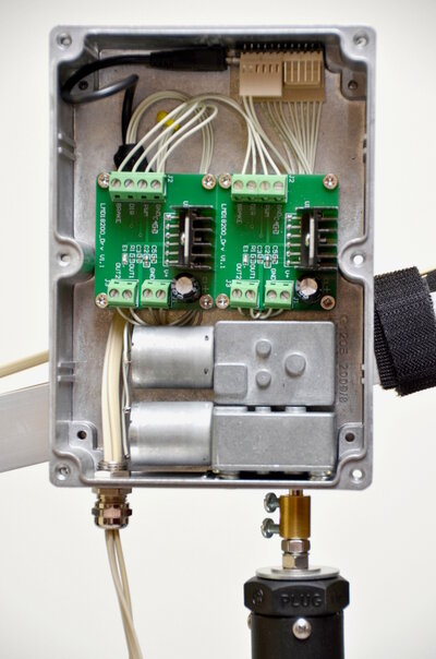
And here it is, our Mini Satellite-Antenna Rototor Mk1:
Full construction details are on our projects page.
In this topic we will discuss all sorts of hints and tips to building and using this rotator. It should be a lot of fun!
36
reviews
Julie and Joe
Friday 23 Feb 2024
Hi Mark,
Congratulations on your build. The rotator6 sketch only activates the beeper during the calibration process. It has the following pin assignments:
//Speaker pins
const int gndPin = 14; //Makes a convenient ground pin adjacent to the speaker pin
const int spkPin = 16; //Attach a piezo buzzer to this pin. It beeps when new calibration data arrives.
We suggest:
1. Check pin 16 for output of 5V pulses
2. Check the piezo device is connected the right way around
3. Check it is an active beeper device, not a just a passive speaker
Hope that helps.
Kind regards and stay safe,
Julie and Joe.
Mark
Friday 23 Feb 2024
I have built the Mk1a, and have version 6 everything works with sensor
all the data points numbers change when moved
but i can't get any output on piezo on pin 14 and 16 on the Arduino PRO Micro
not a beep, did the output pins change for versoin 6?
all the data points numbers change when moved
but i can't get any output on piezo on pin 14 and 16 on the Arduino PRO Micro
not a beep, did the output pins change for versoin 6?
Julie and Joe
Monday 21 Aug 2023
Hi Jack,
Follow the step-by-step instructions here: https://www.sarcnet.org/rotator-mk1.html#SetToWork1
The b command will indicate if the sensor is working: Check all axes to ensure there is a consistent swing in both directions. A 30% offset is acceptable.
The m command and the motors will not function properly until you have performed the sensor calibration - using the c command, including entering your magnetic declination - using the the e command.
Hope that helps.
Kind regards and stay safe,
Julie and Joe.
Jack Kaye
Monday 21 Aug 2023
Is there anyway to test the LMS303HLDC sensor output? My AZ motor does not stop. EL motor works fine. Checked and rechecked all wiring. Sensor is mounted securely on the boom using phone cable about 12in long..AZ Values do change when using the b or m command but the motor does not reflect the changes. Does this indicate the sensor is OK but there is some other problem?? Thanks.
Julie and Joe
Tuesday 12 Oct 2021
Hi Bill,
We just downloaded Gpredict Version 2.3.37 32-bit for Windows and it seems to work OK. There was an issue with some earlier versions with Gpredict not responding correctly to HAMLIB.
The other problem was that Gpredict does not display the rotator position on a Windows PC, although the rotator works fine. Easycomm II rotator position feedback does not work on a Windows PC because of a handshaking issue when using Hamlib with the Arduino IDE USB port driver. A work-around is to use a USB-TTL Converter connected to the TX, RX, GND and VCC pins on the Arduino and changing the code to use the Serial1 port instead of the Serial port. It works OK using the USB port with a Linux PC. This is still the case.
The reason why the USB-TTL interface works is that it bypasses the Windows serial handshaking present on the USB-USB interface.
Hope that helps.
Kind regards and stay safe,
Julie and Joe.
William D Curlew
Tuesday 12 Oct 2021
I built the MK1 and it works a treat. I did have to stay with Gpredict 1.14, and am looking for more clarification as to why the internal Arduino usb/serial port won't work with higher versions of Gpredict/Hamlib. Why does lashing up a seperate serial interface fix this issue? Thanks. Bill KC1JTS
Julie and Joe
Saturday 05 Jun 2021
Hi Mike,
"Once you eliminate the impossible, whatever remains, no matter how improbable, must be the truth." - A.C.D.
Usually those connectors go open-circuit. We never have had one with an internal short. So we have all learnt something.
Good Job!
Kind regards and stay safe.
Julie and Joe.
"Once you eliminate the impossible, whatever remains, no matter how improbable, must be the truth." - A.C.D.
Usually those connectors go open-circuit. We never have had one with an internal short. So we have all learnt something.
Good Job!
Kind regards and stay safe.
Julie and Joe.
mike
Friday 04 Jun 2021
Julie and Joe, my Failed To Start USB error has been resolved. After waiting for and substituting a new eCompass the error persisted. That didn't leave much else to check, as I was confident my wiring was correct. The problem turned out to be the serial cable I used to connect the tracker to the sensor. it was brand new from china, but several of the pins were shorted to themselves inside the molded connector. what garbage. i threw it away and made my own cable up. the USB error disappeared and I now see the compass and accelerometer data on the serial monitor as i should. i can now continue to the calibration process.
Julie and Joe
Monday 24 May 2021
Hi Mike,
Well, this is a new one in over 1000 builds! The USB "Failed To Start" error is not the normal Windows 10 error when the USB controller reports that a USB device has malfunctioned or is drawing too much current. It is a problem with the USB device controller itself. We are not sure what that means. Check you are using a USB 2.0 port. Check that you haven't bricked the Arduino: Load and run the blink sketch, with the LED set for pin 17. We would also check to see if it occurs with just the sensor power connected, then connect the I2C SCL and SDA lines. That might localize, but not solve, the problem. Actually, we think your suspicions are correct: A faulty sensor. About 5% of the sensors we get from China are defective: Usually just one axis is dead, but maybe this one has a power or I/O problem. It is frustrating that there is not more diagnostic information to be sure before having to try substitution. Good luck.
73, Julie and Joe
mike
Monday 24 May 2021
I have a problem with my mk1b build I could use advice on. I'm using the LMS303HLDC and L298N motor controller and Rotator6 software on a Windows 10 machine. The code compiles and uploads to the arduino without errors. My arduino shows up in Device manager as an available serial port, but: ONLY when i do not have the LSM303HLDC connected to the arduino. If i plug the sensor in, the serial port goes away and Device manager shows an unknown USB device and a "failed to start" error. I have triple checked my wiring, it is straight forward and afaik it is correct. Any thoughts other then trying a new sensor?
Julie and Joe
Monday 03 May 2021
Hi Fabio,
It is great to get your feedback. Congratulations on a fine build!
73, Julie and Joe
It is great to get your feedback. Congratulations on a fine build!
73, Julie and Joe
iu5ohc fabio
Monday 03 May 2021
Doing self-construction has always been a passion of mine.
Many thanks to Julie VK3FOWL and Joe VK3YSP of
School Amateur Radio Club Network® for sending me schetch for arduino Rotator6.ino
I had no problem building the basic version of your fantastic Mini Satellite-Antenna Rotator Mk1 idea.
I believe that the adoption of the 3D sensor is highly innovative, which greatly simplifies
the mechanics required for feedback.
In my realization I made only a few changes to increase the rigidity of the project.
I used 2RPM motors with 8mm shaft hub and KFL type ball bearing holders with 8mm bore.
Mounted on metal "L" bracket support.
Julie and Joe
Saturday 02 Jan 2021
Hi Mike,
Regarding your comment about taking the sensor off the boom. In part, the apparent stability of this configuration supports our assumption that the tripod/boom is not rigid. However, it does not (or should not) work as you described: If you remove the sensor from the boom, it is no longer a closed-loop feedback system. If the set point was 0 degrees Azimuth and 0 degrees Elevation, taking the sensor off the boom will have the following effect: Point the sensor West, the boom moves East; point the sensor East, the boom moves West; point the sensor Up, the boom moves Down; and point the sensor Down, the boom moves Up. Only if you hold the sensor at exactly 0 degrees Azimuth and 0 degrees Elevation will the boom stop moving. If it does not work like this, then the wiring is wrong. We suggest you re-check the configuration and operation. Let us know if there is still a problem. Good luck.
73, Julie and Joe.
Julie and Joe
Saturday 02 Jan 2021
Hi Mike,
Thank you for your kind words.
Regarding your problem: The Mini Satellite-Antenna Rotator is a finely-tuned, 2nd-order, closed-loop, feedback control system. It constantly compares the low-pass-filtered, 3D Sensor Az/El data against the set point Az/El and drives the motors using a proportional and integral PWM controller to minimize the offset. The various filter and controller parameters have been set for the system, set up as pictured on our website. However, there are a number of mechanical factors which may cause the controller to oscillate. They are: Different physical configurations, rigidity and backlash in the Az and El axes. Oscillation about the set point does occur even with a perfectly tuned system due to sensor noise, but these are relatively small and infrequent. Larger oscillations will occur if the sensor is mounted more than about 200mm from the El drive shaft: This has the effect of increasing the high-frequency gain of the sensor. Also if the tripod and/or antenna boom mounting are not rigid, or if there is a lot of backlash in mounting arrangement (we mount the boom slightly front-heavy and use 5mm O-rings on the motor shafts to combat the backlash inherent in the motor gearboxes), the unit will oscillate wildly either side of the set point. Check out our videos to see what is normal. Our next post will address your other comment.
73, Julie and Joe.
Mike Funston
Saturday 02 Jan 2021
I have enjoyed this great project. Thank you for all the detail and work you put into sharing this project with other Hams.
One problem that I have is that my trackers (I have two, one with DC and one AC motors) won't remain pointing in one direction. It continuously moves back and forth around the designated setting. Interestingly, if I take to compass/magnetometer off the unit and point it in a particular direction the rotator will move to the designated direction and stop there. it seems to me that the Arduino is working too fast, so it starts re-adjusting before the rotator has completed the last request.
Mike
K4AMP
Julie and Joe
Sunday 09 Aug 2020
Hi Sérgio,
The operation you describe is normal. Without 12V connected the motors may still move due to 5V being supplied to them by the USB. However the drive is very weak. Please describe any remaining problems you may have.
Kind regards,
Julie and Joe.
The operation you describe is normal. Without 12V connected the motors may still move due to 5V being supplied to them by the USB. However the drive is very weak. Please describe any remaining problems you may have.
Kind regards,
Julie and Joe.
Sérgio Batista
Saturday 08 Aug 2020
Hi Julie and Joe, thank you very much for your help.
I did a check on all the wiring and it looks like everything is fine.
I remade some welds and both engines rotate in both directions.
But, I still have problems after finishing the sensor calibration process.
After this process, I disconnect the USB cable and when reconnecting, the AZ motor starts to move slowly according to the position of the sensor.
As described in the Set to Work Instructions (Part 2), there should be no movement of the motors until 12volts is turned on, correct? Just for information, the assembly box is plastic.
I don't now what is wrong.
Julie and Joe
Saturday 08 Aug 2020
Hi Steve,
The motors sometime suffer from dirty commutators and air gaps during transit. The SARCTRAC Manual troubleshooting section describes the problem and a potential fix: https://www.sarcnet.org/sarctrac/SARCTRAC%20Manual.pdf. It says:
1.Motors don’t work when connected to 12VDC: If you bought our kit, the motors are 100% tested prior to shipping. However, during transport, shock and vibration sometimes makes the brushes disconnect from the commutator: See Figure 2 to see how it works. This can be fixed easily by poking a squashed toothpick into the crescent-shaped holes and GENTLY tickling the gold brush wires. Connect the motor to 12VDC, lift and re-seat the brushes until it starts working. In some cases, a spray of Isopropyl Alcohol through the holes can help shift grease on the commutator. Contact us for gearbox issues, BEFORE you open the gearbox.
Regarding the WiFi link: We have used a pair of ESP8266s one as a WiFi Access Point and Telnet Server and the other as a WiFi Client and Telnet Client. It works fine, with the benefit you don't need a WiFi router. We haven't published the code for it, though. The other option is to use a pair of ACP220 modules as mentioned here: https://www.sarcnet.org/rotator-mk2.html#RotatorMk2a, although we haven't tried it, but it should work well. We have tried several Bluetooth modules as well, but only on the SARCTRAC RPi Platform. We concluded that the linux distro we were using didn't support them properly for seria...
Steve McGuire
Saturday 08 Aug 2020
Hi Guys,
I have recently completed my version of the Mini Rotator v1b.
Only problem I had was one motor was DOA, so a replacement was ordered, problem solved.
Thanks so much for sharing this.
I have read in your status reports that some builder/s have used an Esp8266 to replace the usb cable with a wifi link. I too have achieved this to my windows 10 computer.
My question is how did others achieve the link for the wifi network to talk to rotctld?
The way I did this, to me, seems way too complicated and I wish to simplify the setup on my Win10 computer.
Any help is appreciated.
Thanks again,
Steve VK4SMC
Julie and Joe
Thursday 06 Aug 2020
Hi Sérgio,
It could be a couple of things:
1. Check the wiring and the 5V PWM drive signal to the EL motor is present on either pin 9 or 10 as the sensor is pointed up or down.
2. Check the configuration:
//Please uncomment only one of each of the following MotorTypes, SensorTypes and SerialPort types:
//const int MotorType = PWMDIR; //Please uncomment this line for the LMD18200T DC motor driver.
const int MotorType = FWDREV; //Please uncomment this line for the L298N DC motor driver.
//const int MotorType = ACMOTR; //Please uncomment this line for the triac AC motor driver.
//const int SensorType = LSM303D; //Please uncomment this line to use the LSM303D sensor.
const int SensorType = LSM303DLHC; //Please uncomment this line to use the LSM303DLHC sensor.
3. Our Mini Satellite-Antenna Rotator is a closed-loop control system. For stabilized operation the 3D Sensor has to be rigidly connected to the lift arm on the EL shaft, and the AZ shaft has to be rigidly connected to the tripod. Use the bench setup
4. If the motors move when not commanded to do so check the controller input wiring and the ground connection. The controller does not have pull-up resistors and will drive if an input is floating.
5. Complete the https://www.sarcnet.org/rotator-mk1.html#SetToWork2 procedure on the bench before mounting on a tripod.
Hope that helps. Good luck!
73, and keep safe, Julie and Joe
Sérgio Batista
Thursday 06 Aug 2020
Hi Julie and Joe.
I am working in the version with L298N and LSM303DLHC. I did all procedures like recommended, but after the calibration process, I disconnect and reconnect pro micro to the PC via USB port, and the motors start moving slowly. Moving around the sensor, the AZ motor respond both directions, but the EL motor turn only in one direction.
When I disconect everything, and put the set up on the tripod, and turno on the 12v, AZ motor start moving. In the instructions, says that at this point, shouldn't have any movement.
Can you help me please.
Tks
Julie and Joe
Friday 03 Jul 2020
Hi Etienne,
Have a look at https://www.sarcnet.org/rotator-mk1.html#CompilationInstructions
You should see the following tabs in the Arduino IDE:
Rotator6, cal.cpp, cal.h, fil.cpp, fil.h, lsm.cpp, lsm.h, mot.cpp, mot.h, timer.cpp, timer.h, vec.cpp, vec.h - That's 13 tabs. If you have any problems let us know.
Kind regards and stay safe,
Julie and Joe.
Etienne P41E
Friday 03 Jul 2020
Hi all. I am currently working on my Mk1c project I just requested for the sketch and received a nice reply within a day. I'm following the instructions now trying to upload the sketch but getting some error codes when doing so.
The error says.
Rotator6:40:19: error: timer.h:not such a file or directory
compilation terminated.
I dont know if I'm missing something.
Not so familiar with arduino programming.
Just did some basic tutorials.
I hope it's not a big issue.
Thanks for your time and I'll be pending for more information.
73 de P41E
Julie and Joe
Sunday 07 Jun 2020
Hi Peter,
The Rotator6.ino Arduino Sketch supports both LSM303D and LSM303DLHC 3D Sensors.
The lsm.h module defines the LSM303DLHC Registers as 0x19 and 0x1E.
So it looks like you are correct:
1. It is an LSM303DLHC; and unfortunately
2. Something is wrong because all values should change in response to the "b" command when the 3D sensor is moved around.
The I2C bus is obviously working for some register values not others. So the software is working normally, at least in some cases. It is more likely to be a hardware problem. Now, the I2C bus is a high-speed transmission line. Its performance, in your case, appears to be marginal - possibly resulting from noise, due to voltage spikes, or waveform distortion, due to reflections, cross talk or extra line resistance or capacitance. It is unlikely to be power supply noise, e.g. motor commutator noise, as this would not be correlated with the data transfer. Whereas waveform distortion possibly could only effect certain sequences of bit-transitions, eg. Certain bus addresses. There are bus termination resistors on the boards we use (GY-511) as part of the 5/3V level shifting networks. The only things we can think of are:
1. The I2C cable is too long
2. The I2C cable is shielded
3. The I2C bus is not terminated at the sensor
Please check these and let us know.
Kind regards and stay safe,
Julie and Joe
Peter
Sunday 07 Jun 2020
Hi, I am using 10DOF Lsm303d L3gd20 BMP180 Breakout Module from gluckimhaus at ebay.com, but actually there is LSM303DLHC installed as I realized later. Also I2C scanner shows me 0x19, 0x1E, 0x69 and 0x77 devices. It seems that 0x19 and 0x1E is LSM303DLHC, 0x69 is L3GD20 and 0x77 is BMP180. But I am afraid that something is wrong. Debug shows me values e.g. -422,247,-4095,-32623,32451,-32639, where -4095, -32623 and -32639 are always static values during sensor movement. Also during calibration I get again these 3 numbers together with some zeros (4.8,-350.0,-3.0,-4095.0,-32623.0,32559.0,-32639.0,205.0,207.0,0.0,0.0,63.0,0.0). Is my sensor board faulty or what mistake I made? Thanks, PH.
Julie and Joe
Tuesday 07 Apr 2020
Hi Jem,
Your solution is fine, too. It will work so long as the PC USB and 12V supply are both connected. However, we can advise that the 5V outputs from the PC and Motor Driver do not fight and nothing will fail. We left the 5V connection intact so that we could command the system into demo mode and then disconnect the PC. It is a good demo for the kids. If the 12V supply fails, the PC powers everything just fine, but the motors hardly move because they only have 5V drive. We have never seen a PC USB over-current problem report. Hope this helps.
Kind regards and stay safe.
Julie and Joe.
Jem
Monday 06 Apr 2020
Hi, I'm building the 1b version with the L298N. Although it's been queried above, I'm still concerned that the Arduino Vcc is shown connected to the 5v output from the motor driver ( the motor driver onboard 5v jumper is shown as fitted ). This means that the USB supplied 5v is shorted to the 5v output from the motor driver. Not good. They will fight each other and something will fail. I understand that the motor driver should not be powered off the USB 5v because of the current drawn. I therefore believe that the 5v jumper should be left on the motor driver ( to allow the onboard regulator to supply the current for the motor driver ) and the connection between Arduino Vcc and motor drive 5v should be removed. All signals are referenced from a common ground, so they will still be ok. Could someone review my thoughts please ?
Kind regards,
Jem.
Kind regards,
Jem.
Julie and Joe
Wednesday 27 Nov 2019
Hi Piotr,
That is an accurate observation, sir!
If however it is easier for you pointing the sensor upwards, just turn around and do the entire calibration process facing South.
Kind regards,
Julie and Joe.
That is an accurate observation, sir!
If however it is easier for you pointing the sensor upwards, just turn around and do the entire calibration process facing South.
Kind regards,
Julie and Joe.
Piotr
Tuesday 26 Nov 2019
Hi everyone. I have just started building this fantastic equipment. One question concerning calibration. In the youtube video it's recommended to point sensors north ans parallel to magnetic filed inclination, which, in Southern hemisphere, means above horizon. Do I understood well, that here, in northern hemisphere, I should point sensor towards north and slightly below horizon (magnetic inclination is 69,34)
Denis Brown
Wednesday 28 Aug 2019
Ouch!! Thanks very much for the detailed analysis... it is a lot more complex than I had first imagined! Back to the drawing board.
On a brighter note you'll have had input from Robert VK6FRDM who is very well advanced with constructing both Mk1 and Mk2. To the extent that he has demonstrated Mk1 to a group of school students and has a toe in the door for future demos and possibly establishing a continuing group. Robert's rotators were both on display at the most recent HAMfest here in Perth where they attracted considerable interest from fellow operators. I too will have a Mk1 and Mk2 "in the fullness of time" but a few other household projects ahead of them in the pipeline.
73, Denis
Julie & Joe
Tuesday 27 Aug 2019
Hi Denis,
You wrote in another forum:
“I wanted to comment that in my build of the Mk1 rotator I am going to include an LM7809 style voltage regulator fed from the 12-volt motor power source, feeding into the Pro Micro's RAW pin. The idea here is that in the event that 12 volts is applied and the USB power disappears - flat laptop battery, disconnected USB cable, etc - there is no concern about the driver board feeding back into the Arduino's I/O pins. In the absence of a controlling PC, the Arduino would enter a pause state so no danger of the motors being activated and creating havoc.”
This is a very interesting subject indeed!
The Pro Micro can run off the USB Port. But powering other things as well as the Pro Micro requires the J1 jumper, which bypasses the on-board 5V regulator and supplies 5V directly from the USB Port.
The L298N Motor driver logic will not run off the Pro Micro regulator. The regulator will get hot. So, the J1 jumper was used.
The L298N Motor driver has its own on-board 5V regulator, but it only works when 12V is connected.
With the current wiring, which has a 5V link from the Pro Micro to the Motor Driver:
1. If you supply USB and 12V, everything works fine and you can control the rotator from the PC.
2. If you supply USB only, everything works except the motors are only driven with 5V. They may turn a bit, but not much, which surprises some readers. So not good.
3. If you supply 12V only, everything works, but there is no c...
Denis VK6AKR
Saturday 24 Aug 2019
Thanks Julie, Joe
Was blissfully unaware of the other ways to brick a Pro Micro. Always learning. Yes the un-bricking details would be useful on the website, I think.
73, Denis
Was blissfully unaware of the other ways to brick a Pro Micro. Always learning. Yes the un-bricking details would be useful on the website, I think.
73, Denis
Julie & Joe
Saturday 24 Aug 2019
Hi Denis,
Congratulations to you and Robert for your success. We would love to see/publish the pictures. The WA VHF Group is again leading the way.
Yes the Pro Micro boot loader is both a blessing and a curse. It is an especially "fun" way of picking up any simple coding errors in the constructor of a C++ class object. Thank you for reminding us about it. We will publish the "unbricking" procedure on the website. We must have just assumed everyone could do it with their eyes closed.
Regarding the MK2: Please see our Mini Satellite-Antenna Mk2 forum.
As always, please let us know how we can collaborate with you guys on any future projects.
Kind regards and keep in touch,
Julie and Joe.
Denis VK6AKR
Saturday 24 Aug 2019
Hello all,
Fellow WA VHF Group member Robert VK6FRDM and I are building Mk1 rotators, and have the bits together for the Mk2 version as well. Just letting you know that Robert has beaten me to the finish line and demonstrated it yesterday at our second "Activity Day" for July. Several photos taken which I think Robert will send later.
The Mk2's sprockets and chains caused us some interesting hassles sourcing, but we will be getting there by boring out the bosses of some Australian-sourced parts to suit our 25mm tubing.
Finally a caution! Arduino Pro Micro's can be "bricked" quite easily by attempting to upload code to the incorrect version! I.e. inadvertently selected the 8MHz version in lieu of the 16MHz version. Happily they can be "un-bricked" with a little fiddling but better not to have to tread that path. Look carefully at the oscillator for frequency. In our cases the Arduinos were not clearly marked in the silk screen.
73, Denis VK6AKR
Julie & Joe
Saturday 24 Aug 2019
Yes Bob, it is actually very important. It is all about reducing the torsional moments exerted on the motor bearings. When the antenna is mounted on one side of the rotator there is an extra rotational force, or torque, on the azimuth bearing. Any distance between the azimuth and elevation axes, or moment, increases this torque. The motors are only light duty and they actually only have brass bushes, not real bearings. So the more torque - the more wear and tear.
Regards,
Julie and Joe
Regards,
Julie and Joe
VK2BYF
Saturday 24 Aug 2019
Is there a reason for mounting the elevation motor near the bottom of the die cast box rather than at the top? I was thinking of mounting the elevation motor in the centre near the top to allow the antenna to be mounted closer to the pivot point and therefore requiring less counterbalancing weight on the elevation arm. So long as the antenna reflector clears the box there should be no detuning of the antenna.
Bob vk2byf
Bob vk2byf